
Computer vision cad models

a computer vision and cad model technology, applied in the field of computer vision cad models, can solve the problems of not being able to use other objects in engineering steps, unable to use marker-less vision-based applications in industrial environments, and not being able to generalize most engineering steps

Inactive Publication Date: 2010-10-14
MVTEC SOFTWARE
View PDF7 Cites 25 Cited by
  • Summary
  • Abstract
  • Description
  • Claims
  • Application Information

AI Technical Summary

Benefits of technology

[0007]Additionally, a tool that allows the creation of a CV-CAD model from the standard CAD model of the object and at least one image of that object is proposed. The only requirement is that the image or images of the object are registered to the CAD model. These data are processed and as a result, additional information is enclosed in the standard 3D model, which allows the direct integration of vision-based applications. The combination of geometric data and computer vision data is done by agents, which can operate locally or globally and can generate pose hypotheses and confidence values.
[0018]In summary, the invention provides the following features or advantages:
[0028]The agents of the CV-CAD model (locally) interact with each other to achieve optimum recognition times, optimum recognition performance, and optimum pose accuracy.

Problems solved by technology

Despite the strong research advances in computer vision and pattern recognition of the last decades, marker-less vision-based applications are rare in industrial environments.
This is mainly due to the expensive engineering step needed for their integration into an existing industrial workflow.
The problem is that the result of such an engineering step typically cannot be used for other objects, for example, if the industrial object is not piecewise planar and not well textured.
Consequently, most of the engineering steps are not general and cannot be easily adapted to new applications.
In fact, they are often only valid for limited object categories, restricted viewpoints (even within the same category of objects), special illumination conditions or camera resolutions and lenses.
Edge features are more difficult to handle, but also some methods have been published [7], [11].

Method used


Image

  • Computer vision cad models
  • Computer vision cad models
  • Computer vision cad models

Examples


Embodiment Construction

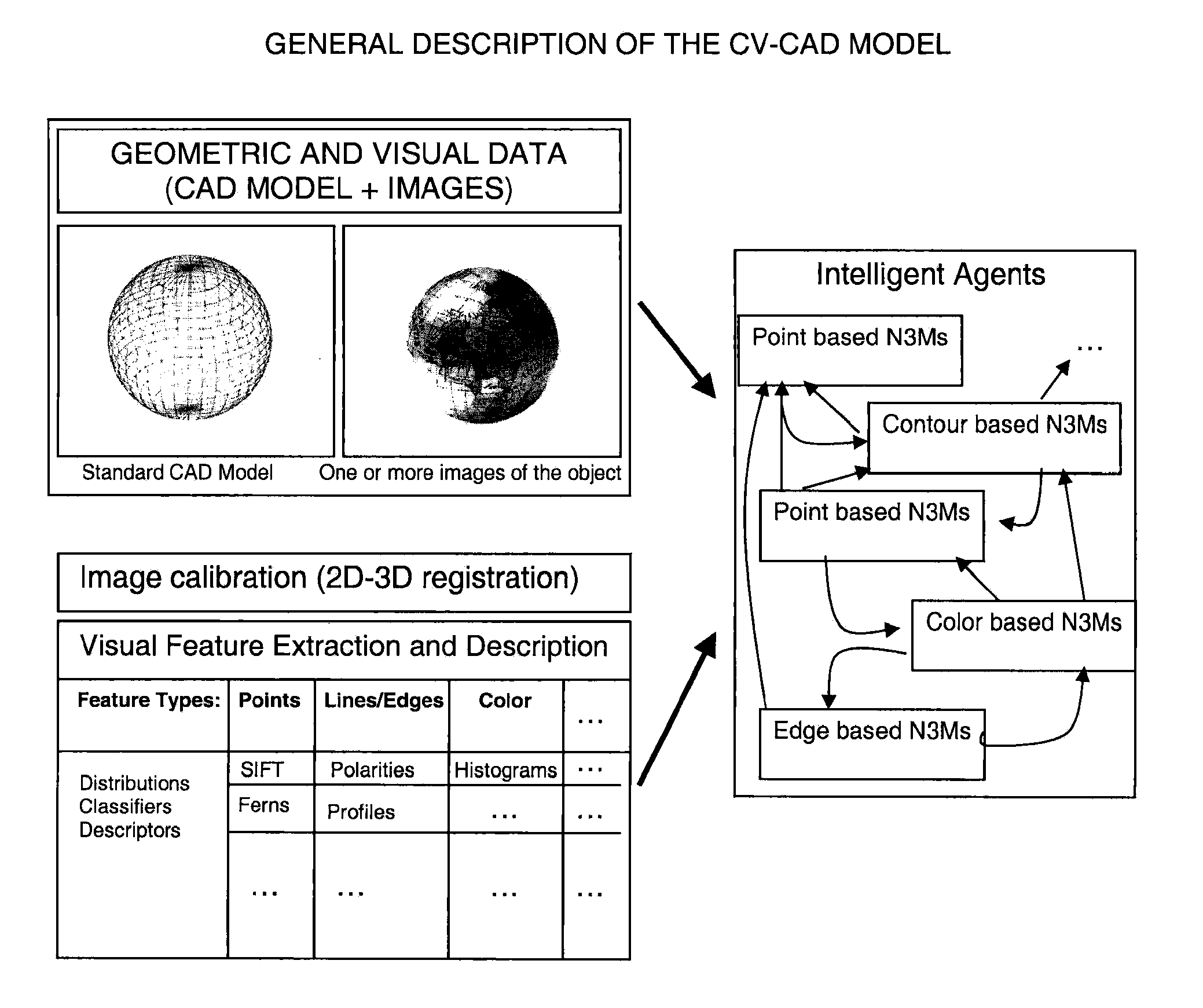
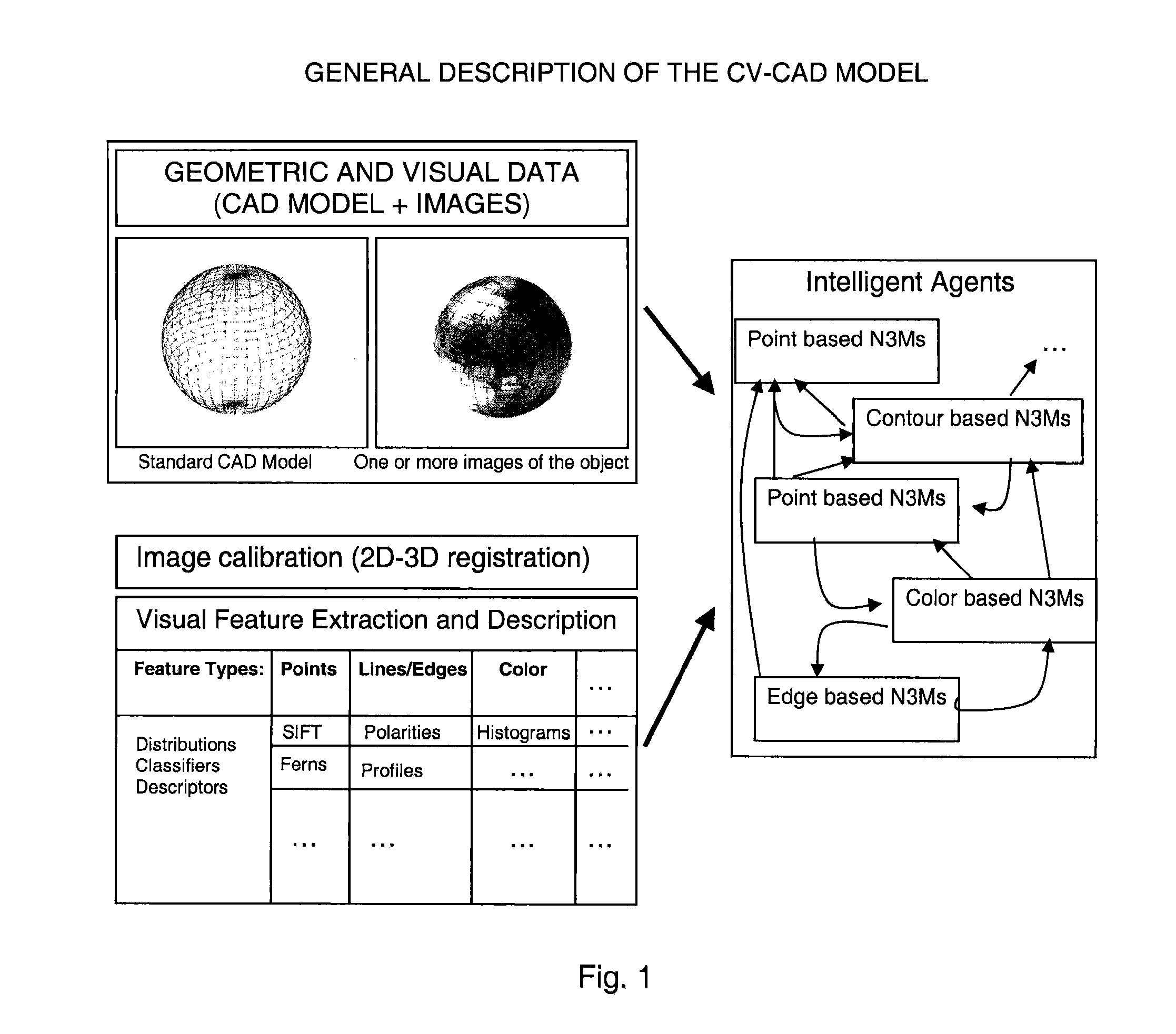
[0039]In the first step, a CAD model of an object must be textured. For instance, this can be done by registering images of the object with the CAD model, e.g., with the method described in [18]. If a textured CAD model is already available, the first step does not need to be performed. In a second step, for each part of the textured CAD model the optimal computer vision features are trained. Optimal means that the computer vision features extracted and computed for the single parts are the most robust and stable features for object recognition and pose estimation. In the training step, different other aspects of computer vision, like, e.g., self-occlusion of the object, different lighting conditions, appearance and viewpoint changes of the object parts, etc., can be considered as well.

[0040]Computer vision features can be split into detectors, like points, corners, segments, lines, edge profiles, colors, texture, contours, and the like, and descriptors, like SIFT, Randomized Trees,...


PUM


Abstract

The CV-CAD (computer vision-computer-aided design) model is an enhanced CAD (computer-aided design) model that integrates local and global computer vision data in order to represent an object not only geometrically but also in terms of computer vision. The CV-CAD model provides a scalable solution for intelligent and automatic object recognition, tracking and augmentation based on generic models of objects.

Description

BACKGROUND OF THE INVENTION[0001]Despite the strong research advances in computer vision and pattern recognition of the last decades, marker-less vision-based applications are rare in industrial environments. This is mainly due to the expensive engineering step needed for their integration into an existing industrial workflow. Typically, an expert decides which algorithm is most suited for each specific application. The decision is generally based on not only the geometry and the appearance of the object to be recognized by the application, but also the illumination conditions and the optical sensor (the camera and the lens) that are used.[0002]For example, when the object is piecewise planar and textured, the expert may select methods based on feature point detection and / or template-based tracking to recognize the object in a single image or an image sequence. He manually tests different visual feature detectors and descriptors, and then selects the method that provides the optimum...

Claims


Application Information

Patent Timeline
IPC IPC(8): G06T15/00G06V10/40
CPCG06K9/46G06F17/50G06T7/0046G06K9/6292G06T7/75G06V10/40G06V10/809G06F18/254G06F30/00
Inventor BEN-HIMANE, SELIMHINTESTROISSER, STEFANNAVAB, NASSIR
Owner MVTEC SOFTWARE
Learn More