Method for Supporting a Stretched Membrane Solar Trough Collector

Inactive Publication Date: 2010-10-14
HARRENSTIEN HOWARD P +1
View PDF5 Cites 18 Cited by
  • Summary
  • Abstract
  • Description
  • Claims
  • Application Information

AI Technical Summary

Benefits of technology

[0007]The present invention relates to improvements in the support structure or “frame,” of a linearly tensioned thin-film solar collector or concentrator that significantly increases the length that the reflective thin-film membrane may span. A longer span allows for a reduced number of support posts, thereby decreasing the cost and enabling the frame to be custom fitted to a supporting roof structure. Additional features decrease wind-related forces making the current device especially well-suited to roof-top installations. Further, a frame structure allows for the replacement of the thin-film membrane without replacement of the entire trough unit.
[0008]The invention provides for a novel truss system comprising of side-beams, ridge-caps, tensioned cables, tension arms or end beams, and posts. The side beams can be configured to deflect wind, and in combination with a convex cover for the collector, significantly increase the wind resistance over other designs.
[0010]Ridge-caps are placed across the collector preferably at a fixed spacing. End ridge caps are placed over the end forms. Cables connect opposite corners diagonally, where the ridge-caps and end ridge-caps are connected to the side-beams. The ridge-caps end ridge-caps and cables form a truss system in conjunction with the side-beams. This provides a very strong, light-weight structure that may be used over a long span and has increased resistance to wind and earthquakes.
[0011]Shaping forms, or ribs, that aid the linear tensioned thin-film reflector in keeping the desired shape may be placed along the reflector, preferably under the ridge-caps. The ridge caps may also support a ridge pole or poles for supporting a tensioned thin-film cover with a convex profile, which, in combination with the side beams and the curved lower surface of the tensioned thin-film reflective membrane reduces the wind forces on the reflector and thus on any roof structure on which the device is installed.
[0012]The length of the support structure may be varied to customize it for specific installations. For example, beams in commercial buildings may have custom spacing or the angle of the collectors on the rooftop could require custom lengths. While the side beams could simply be manufactured to the desired length for the particular installation, it is also possible to construct telescoping beams that allow for varied lengths.

Problems solved by technology

The length of the span between supports is one of the most important factors of weight and cost, since the end supports are among the heaviest and most expensive components of the system.
This makes it very difficult to use a torsion tube to span large distances and thus reduce the cost of a linearly tensioned thin-film concentrator.
Second, the buckling strength of a long torsion tube is generally low and inversely proportional to the square of the length.
In addition, linearly tensioned thin-film reflectors place the tube in compression, which significantly increases the buckling forces on the torsion tube.
While the buckling strength will increase with fixed ends, it is still of major concern.
The increased weight and cost of a tube to span a long distance often makes it impractical for use in spanning long distances.
Third, using a long torsion tube in the center of a collector pair makes it difficult to attach additional components on the outside edges of the collector pair.
One specific limitation this causes is a difficulty to securely attach wind spoilers to deflect wind at the edges of the collectors.

Method used


Image

  • Method for Supporting a Stretched Membrane Solar Trough Collector
  • Method for Supporting a Stretched Membrane Solar Trough Collector
  • Method for Supporting a Stretched Membrane Solar Trough Collector

Examples


Embodiment Construction

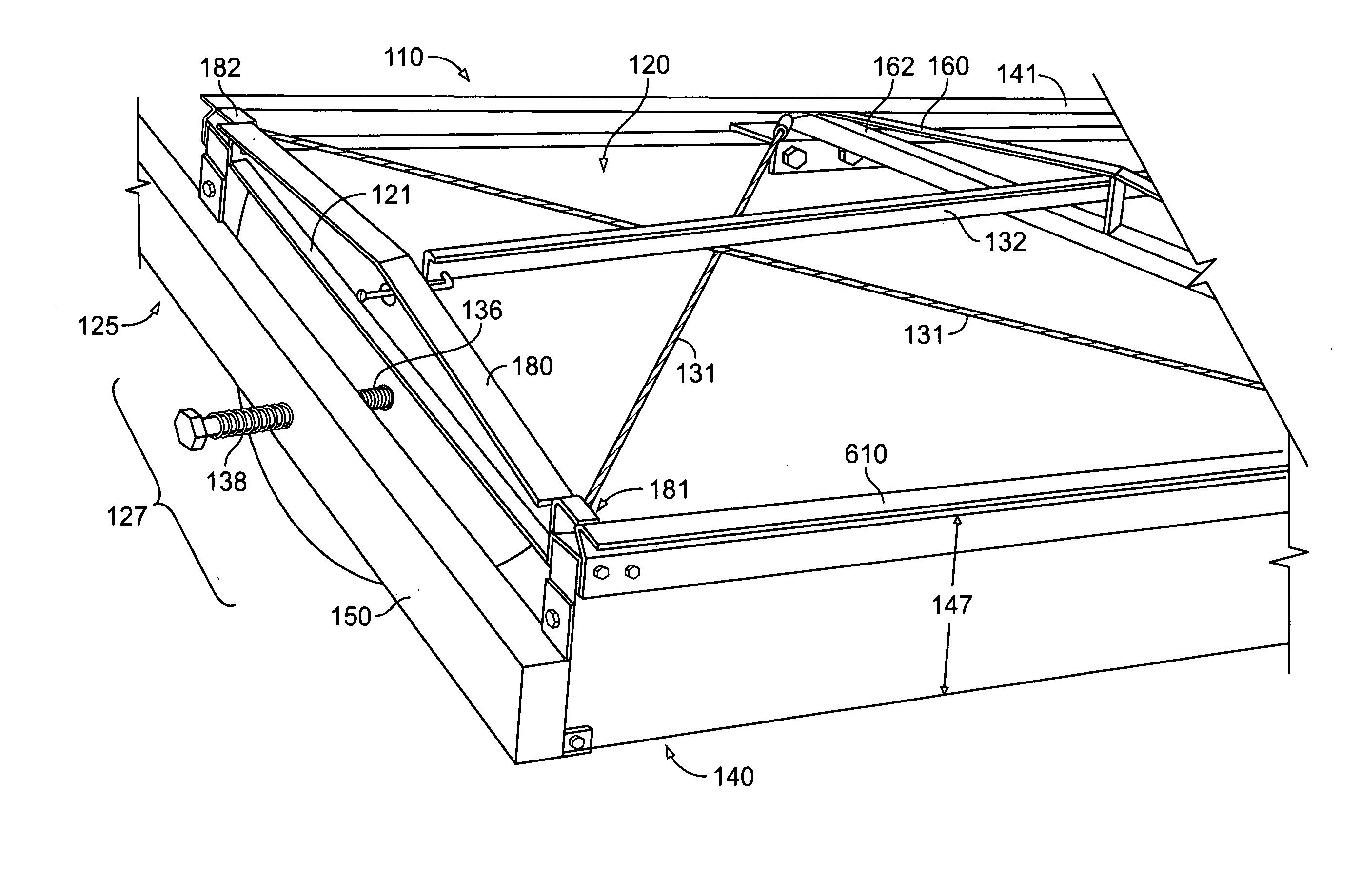
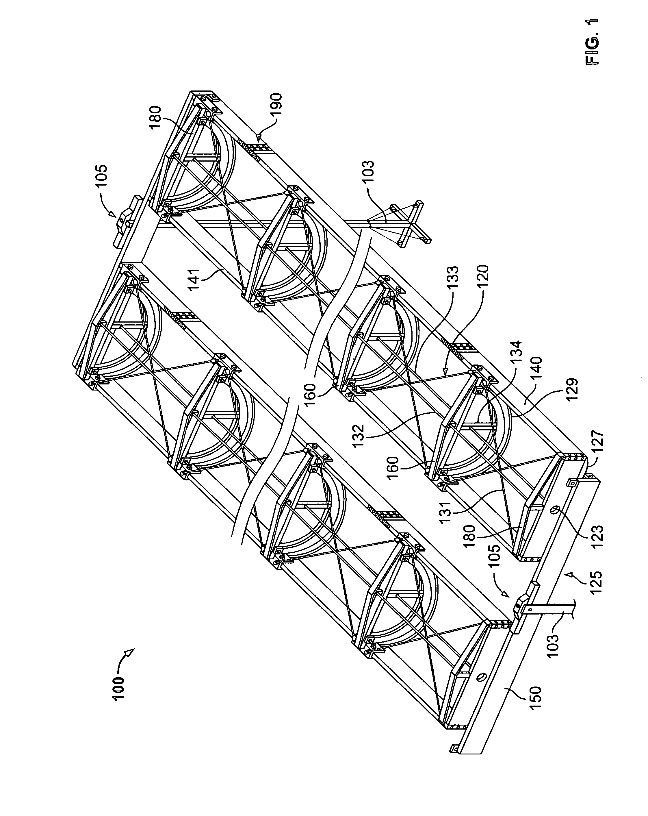
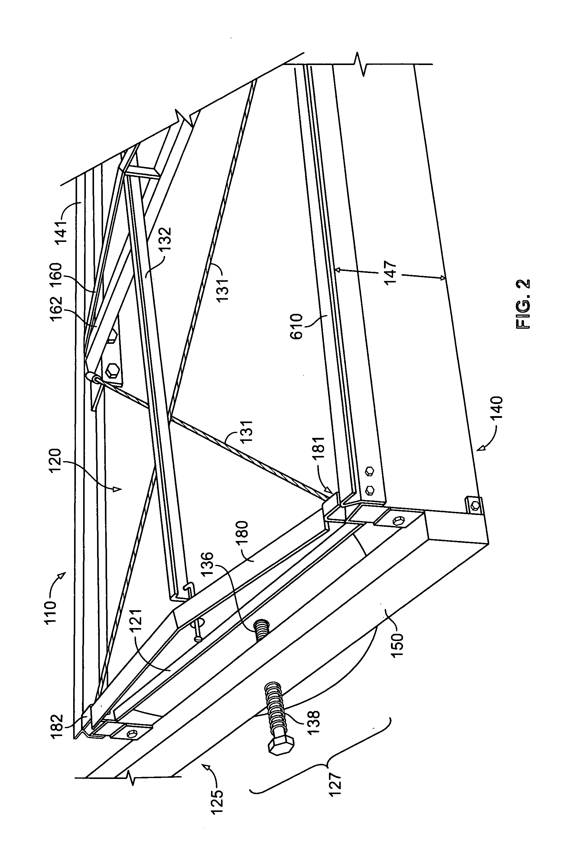
[0032]With reference to FIGS. 1-4 the solar collector 100 device includes a support means for supporting one or more frames 110, which can be a braced post 103 or other appropriate structure.

[0033]The frame 110 or frames is supported by a tension arm assembly 125 that may include extensions 127. The tension arm assembly 125 is rotably attached 105 to the post 103 so as to allow the frames 110 to be moved under the control of a control system (not shown) so as to maintain optimal position with respect to the sun and to avoid damage from high winds, as further described below. Multiple frames may be supported on a single tension arm assembly 125, and would be balanced so as to allow for ease of rotation. Alternatively, each frame could be supported rotably on the tension arm or other support structure individually.

[0034]The frames include two light-weight side beams 140, 141, each defining a first end 143, 145 and a second end 144, 146. The frame 110 also includes two end beams 150, 1...


PUM


Abstract

An improved solar reflector with a frame structure suitable for spanning longer distances that utilizes light-weight side beams, ridgecaps and tensioned cables to form a truss-system.

Description

BACKGROUND OF THE INVENTION[0001]The invention relates to a solar collector in the nature of an arcuate generally parabolic surface which concentrates solar radiation upon an energy absorbing target which is located at the focus of the parabola.[0002]Linear tensioned thin-film, or “membrane” concentrators have many advantages over more traditional designs utilizing rigid backed reflective material. Most importantly they weigh less. The reduced weight allows larger collectors to be mounted on a pair of posts with a specified strength and roofs with a given specified load. In addition, multiple concentrators can be controlled for example rotated, with less energy due to the lower weight. Thus, fewer motors may be required to move them into a desired position.[0003]Linearly tensioned thin-film concentrators are typically supported at each end. The length of the span between supports is one of the most important factors of weight and cost, since the end supports are among the heaviest a...

Claims


Application Information

Patent Timeline
IPC IPC(8): H01L31/00F24S23/70
CPCF24J2/145F24J2/4638F24J2/50F24J2/541F24J2002/5286H01L31/0547Y02E10/45Y02E10/47Y02E10/52Y02B10/12H02S20/23H01L31/0232F24S23/745F24S30/425F24S40/85F24S80/58F24S2025/017
Inventor HARRENSTIEN, HOWARD P.BRONSTEIN, ALLEN I.
Owner HARRENSTIEN HOWARD P
Why Eureka
Try Eureka