
Method of manufacturing medical instrument and medical instrument

a manufacturing method and technology of medical instruments, applied in the direction of manufacturing tools, surgical forceps, surgery, etc., can solve the problems of difficult assembly of the scissor mechanism, and achieve the effect of easily cutting off an object and highly accurate assembly

Inactive Publication Date: 2010-09-30
TERUMO KK
View PDF7 Cites 34 Cited by
  • Summary
  • Abstract
  • Description
  • Claims
  • Application Information

AI Technical Summary

Benefits of technology

[0010]It is an object of the present invention to provide a method of manufacturing a medical instrument having a scissors mechanism and which is assembled highly accurately for easily cutting off an object. A further object of the present invention is to provide such a medical instrument itself.
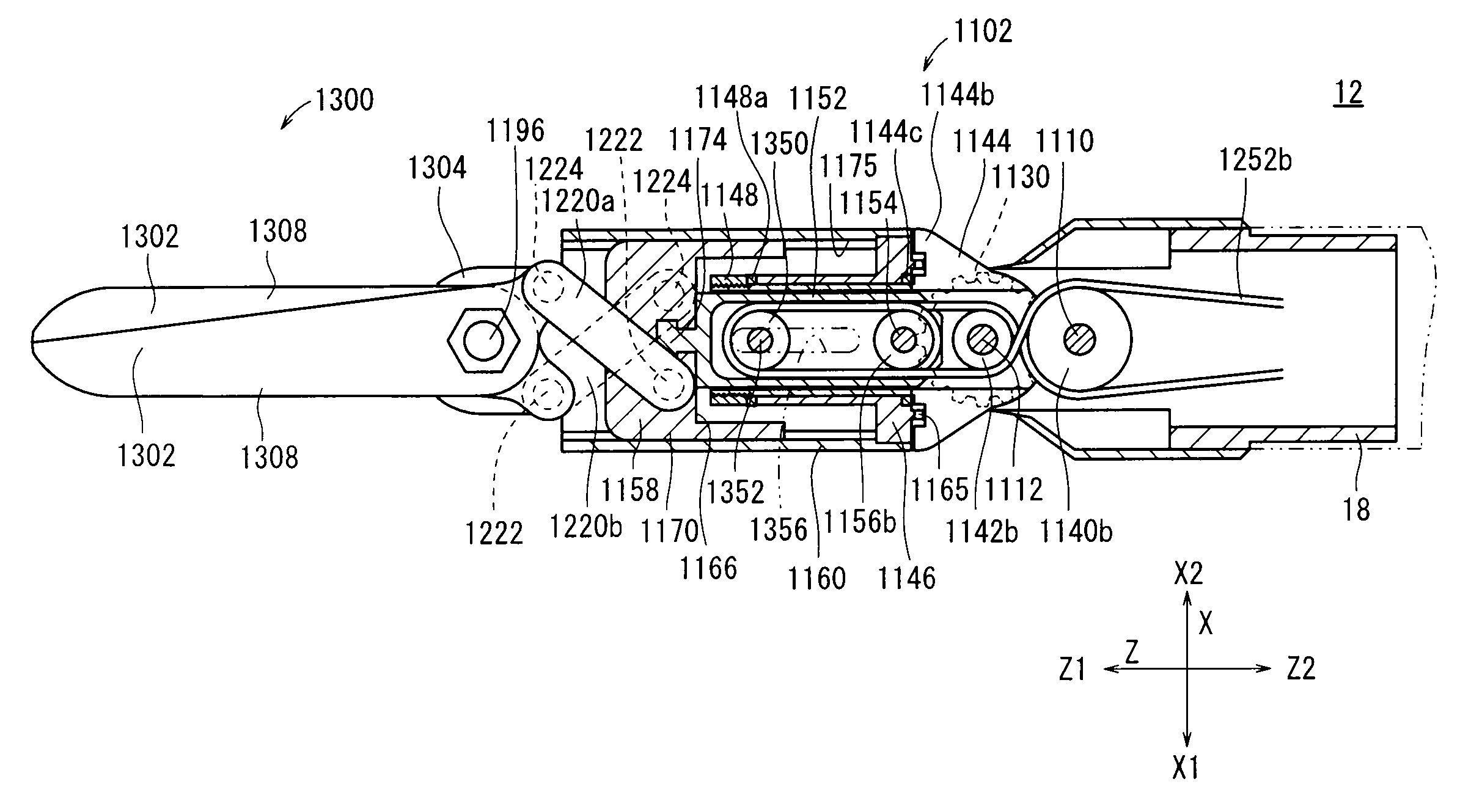
[0012]The first, second, and third steps do not need to be carried out in a small space, and there are no interlinking members involved in the first, second, and third steps. Therefore, the structural body can be assembled highly accurately. In the fourth and fifth steps, the pin is fitted into the shaft hole of the bolt in order to assemble the structural body into the connecting tube. The structural body and the connecting tube can thus be assembled together easily, while the openable and closable members of the structural body are kept in a sliding state highly accurately.
[0013]The method may include, after the fourth step and before the fifth step, a spacer insertion step of placing a spacer in a gap between the structural body and an inner surface of the connecting tube. The spacer, which is placed in the gap, makes it possible for the structural body having the fixed openable and closable members to be adjusted in position and secured in the connecting tube.
[0015]The openable and closable members are angularly movably supported by the pin while being kept in a predetermined sliding state. The structural body can easily be assembled using the shaft hole, which is defined axially through the bolt.
[0016]The medical instrument may further comprise a spacer disposed in the connecting tube and placed in a gap between the structural body and an inner surface of the connecting tube, the pin being inserted in the spacer. The spacer, which is placed in the gap, makes it possible to prevent the structural body having the fixed openable and closable members from being displaced within the connecting tube.
[0018]With the method of manufacturing a medical instrument and the medical instrument according to the present invention, since the first, second, and third steps do not need to be carried out in a small space, and since there are no interlinking members involved in the first, second, and third steps, the structural body can be assembled highly accurately. In the fourth and fifth steps, the pin is fitted into the shaft hole of the bolt in order to assemble the structural body into the connecting tube. The structural body and the connecting tube can thus be assembled together easily, while the openable and closable members of the structural body are kept in a sliding state highly accurately.

Problems solved by technology

If a scissors mechanism is to be installed on the tip end of such a distal-end working unit, then the scissors mechanism is difficult to assemble, and the worker needs to be highly skilled in order to assemble the cutting edges of the scissors mechanism accurately on the distal-end working unit with no gap between the cutting edges.

Method used


Image

  • Method of manufacturing medical instrument and medical instrument
  • Method of manufacturing medical instrument and medical instrument
  • Method of manufacturing medical instrument and medical instrument

Examples


Embodiment Construction

[0048]Manipulators according to embodiments of the present invention will be described below with reference to FIGS. 1 through 28.

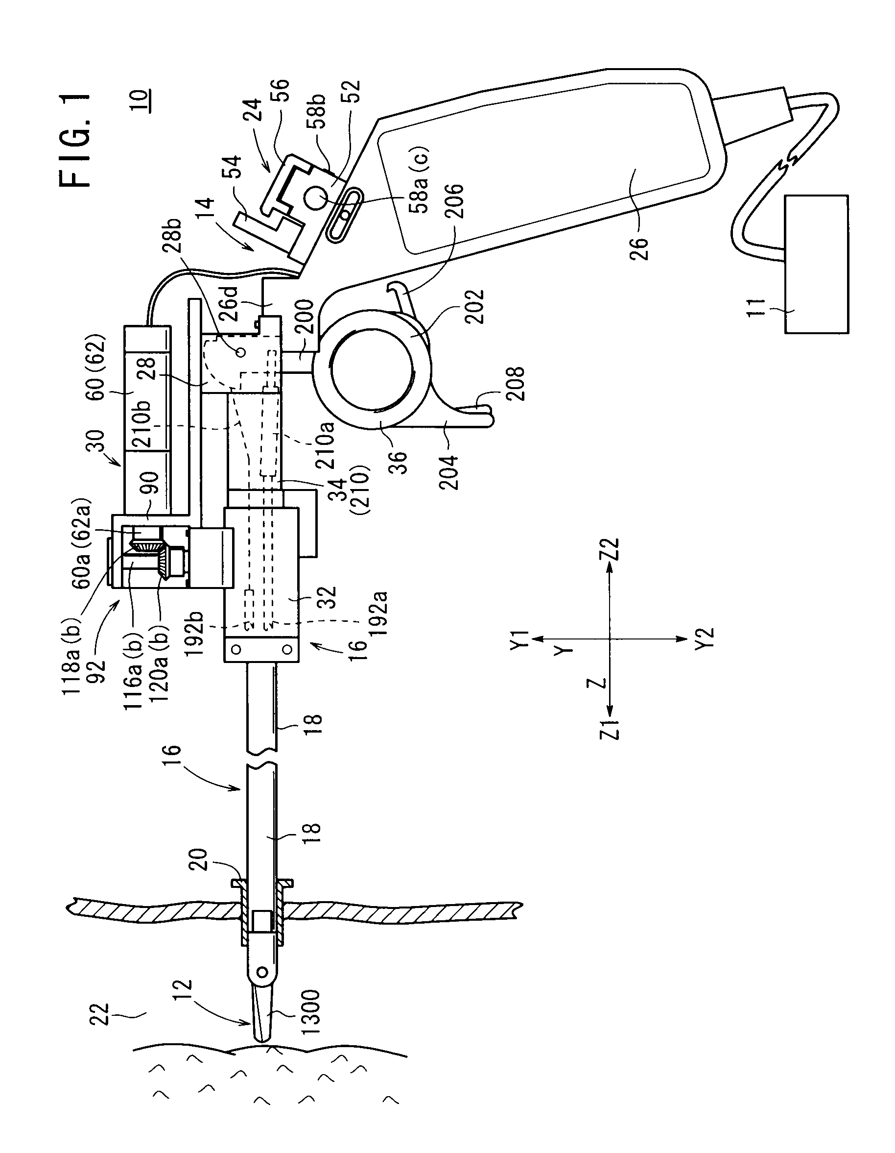
[0049]As shown in FIG. 1, a manipulator 10 according to an embodiment of the present invention is electrically connected to a controller 11. The manipulator 10 is basically a medical manipulator for use in surgical operations.

[0050]The controller 11, which electrically controls the manipulator 10, is connected by a connector to a cable, which extends from the lower end of a grip handle 26 of the manipulator 10. The controller 11 is capable of independently controlling a plurality of manipulators 10 at the same time, although the controller 11 also can control a single manipulator 10, as shown in FIG. 1.

[0051]The manipulator 10 includes a distal-end working unit 12 having on its tip end a scissors mechanism (structural body) 1300 for cutting off a portion of a living body or a suture.

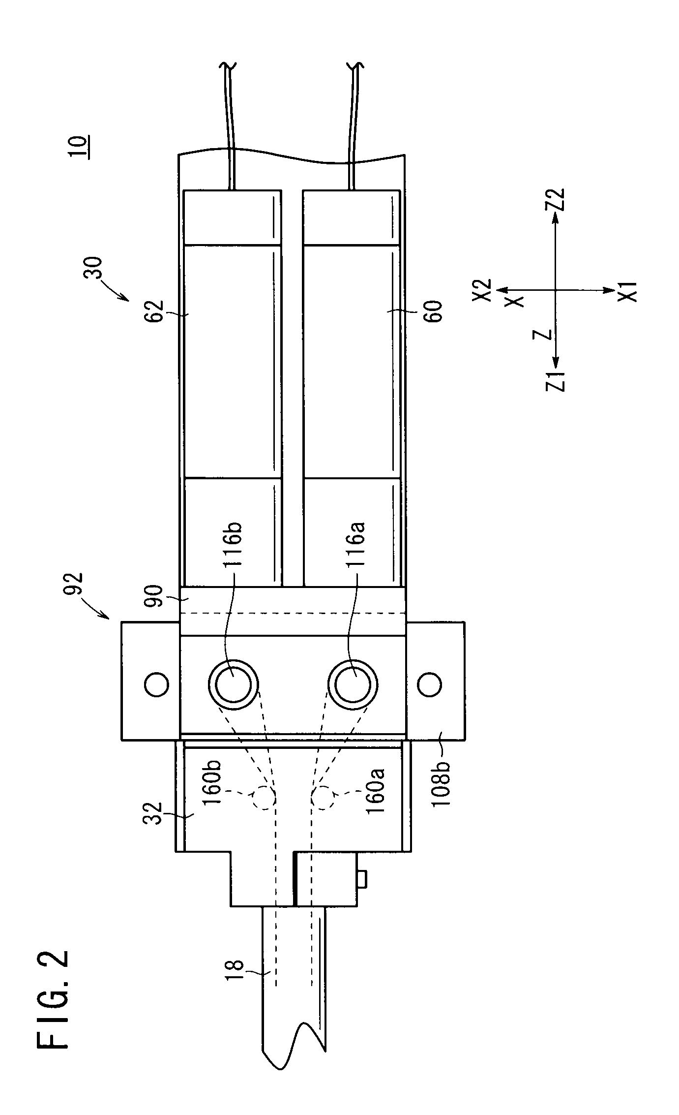
[0052]As shown in FIGS. 1 and 2, the manipulator 10 includes an operating...


PUM


Abstract

Scissors on the distal end of a medical instrument are assembled highly accurately for cutting an object with ease. A scissors mechanism is assembled as a unit. The scissors mechanism has a pair of end effector members openably and closably fastened at proximal ends thereof by a bolt and nuts, while being held in a predetermined sliding state. The bolt has a central hole defined axially therethrough. The scissors mechanism is inserted into a tubular structure of a cover, which is coupled to the distal end of a joint shaft, and the end effector members are connected to a driven plate by links. A spacer is placed in a gap between the scissors mechanism and an inner surface of the cover. A pin is inserted, from an outer surface of the cover, into a hole of the cover and the central hole of the bolt.

Description

CROSS-REFERENCE TO RELATED APPLICATION[0001]This application is based upon and claims the benefit of priority from Patent Application No. 2009-080479 filed on Mar. 27, 2009, in the Japan Patent Office, of which the contents are incorporated herein by reference.BACKGROUND OF THE INVENTION[0002]1. Field of the Invention[0003]The present invention relates to a method of manufacturing a medical instrument having a pair of scissors on the distal end of a shaft for cutting off a portion of a living body, a thread, etc. The invention also relates to such a medical instrument itself.[0004]2. Description of the Related Art[0005]According to a laparoscopic surgical operation process, a certain number of small holes are opened in the abdominal region, for example, of a patient, and an endoscope and manipulators or forceps are inserted into the holes. The surgeon performs a surgical operation on the patient with the manipulators or forceps while watching an image captured by the endoscope and d...

Claims


Application Information

Patent Timeline
IPC IPC(8): A61B17/32B23P11/00
CPCA61B17/29A61B19/22Y10T29/49826A61B2017/2929A61B2017/2939A61B2017/2927A61B34/70
Inventor JINNO, MAKOTOYUNO, YOSHIAKI
Owner TERUMO KK
Learn More