
Image forming apparatus

a technology of image forming apparatus and forming material, which is applied in the direction of electrographic process apparatus, instruments, optics, etc., can solve the problems of increasing the disposition cost of optical sensors, and reducing the efficiency of image recording. , to achieve the effect of increasing costs and not lowering image productivity

Inactive Publication Date: 2010-09-30
CANON KK
View PDF23 Cites 14 Cited by
  • Summary
  • Abstract
  • Description
  • Claims
  • Application Information

AI Technical Summary

Benefits of technology

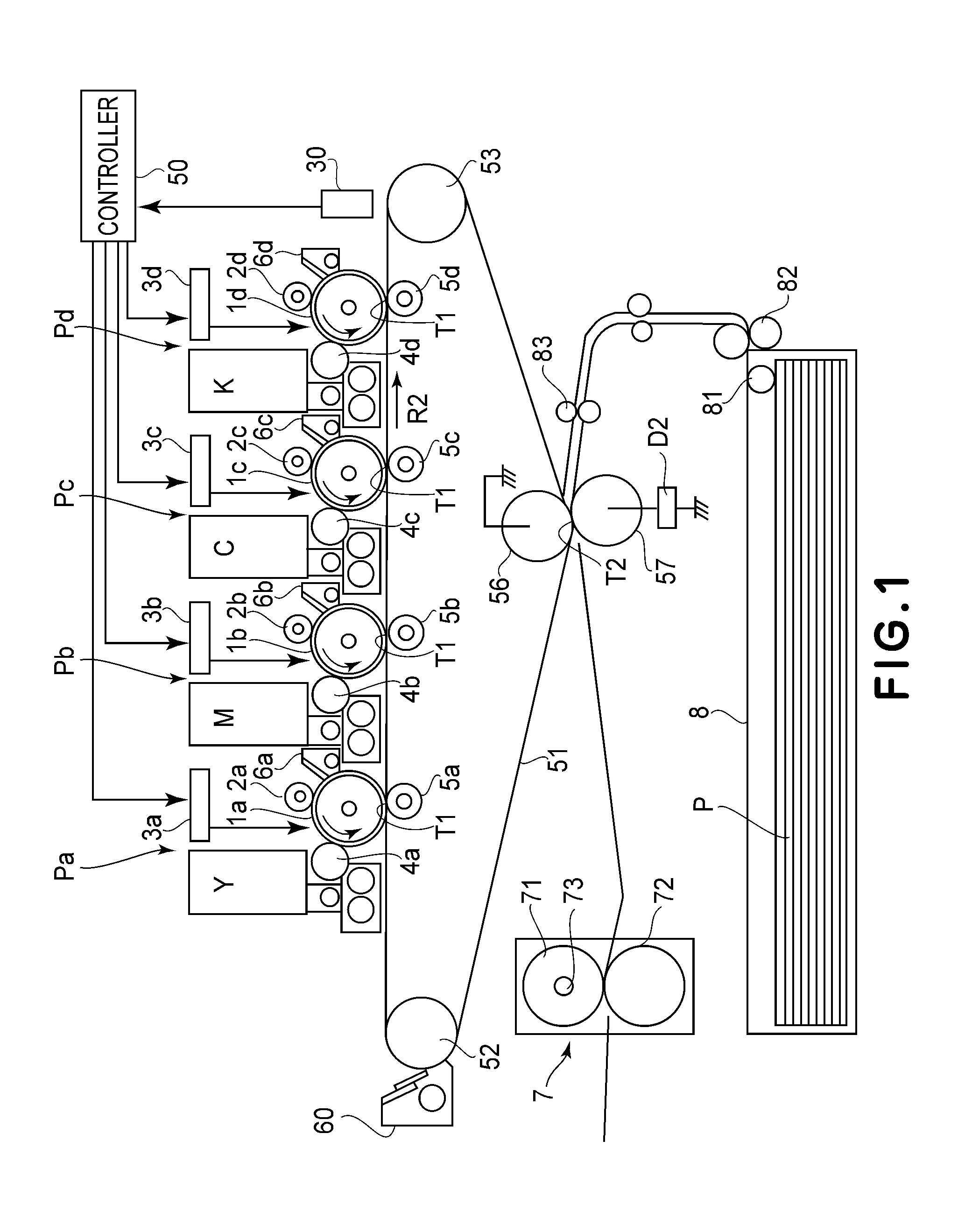
The present invention provides an image forming apparatus that can execute a test image measuring mode without reducing image productivity and increasing costs. The apparatus includes a toner image forming device that forms a first color test image and a second color test image with different screen angles and ruler settings, a detecting device that detects the distribution of heights of the test images, and a control device that adjusts the toner image forming condition based on the detected distribution. This allows for efficient and accurate measurement of the test images without impacting the overall image quality and productivity.

Problems solved by technology

For this reason, every execution of the test image measuring mode, the recording material is consumed and an unnecessary image is output.
However, in the control described in JP-A 2007-65641, test images of yellow, magenta, cyan and black are formed in a line, so that these test images are not accommodated within an interval between adjacent images (so-called sheet interval).
Further, in the case where a plurality of optical sensors is disposed and detects a plurality of colors of test image in parallel, a disposition cost of the optical sensors is increased and a variation in characteristic of the optical sensors results in an error of color adjustment.

Method used


Image

  • Image forming apparatus
  • Image forming apparatus
  • Image forming apparatus

Examples


embodiment 1

[0093]FIGS. 7(a) and 7(b) are explanatory views each showing an arrangement of patch toner images in Embodiment 1. FIGS. 8(a) and 8(b) are explanatory views each showing an individual patch toner image. FIG. 9 is an explanatory view of a superposed patch toner images. FIGS. 10(a) and 10(b) show a yellow patch toner image detection signal and a magenta patch toner image detection signal, respectively. FIG. 11 is a superposed patch toner image detection signal. FIG. 12 shows a result of frequency analysis of the superposed patch toner image detection signal. FIG. 13 is an explanatory view of integral processing. FIG. 14 is a graph showing a relationship between an integrated value and a toner amount.

[0094]As shown in FIGS. 7(a) and 7(b), in this embodiment, a yellow patch toner image CPY and a magenta patch toner image CPM are formed superposedly at an interval (spacing) between print images. Each of the yellow patch toner image CPY and the magenta patch toner image CPM is formed in a...

embodiment 2

[0115]FIG. 15 shows a result of frequency analysis of detection signal of superposed patch toner images in Embodiment 2.

[0116]In Embodiment 1, the example in which the superposed patch toner images of yellow and magenta have the same screen ruling of 200 lines / inch but have the different screen angles was described. In Embodiment 2, the patch toner image of yellow having the screen ruling of 160 lines / inch and the patch toner image of magenta having the screen ruling of 200 lines / inch are superposed. The screen angle is 90 degrees for yellow and 45 degrees for magenta similar as in Embodiment 1. Constitutions and control except for the screen angle are similar to those in Embodiment 1, thus being omitted from redundant description.

[0117]The spatial frequency of the yellow patch toner image having the screen ruling of 160 lines / inch is 0.159 mm (25.4 mm / 160 lines). The spatial frequency of the magenta patch toner image is 0.170 mm (25.4 mm / 200 lines / sin)45° similarly as in Embodiment...

embodiment 3

[0122]In Embodiment 3, control using the patch toner images in the image forming apparatus using a recording material conveying member will be described. The image forming apparatus using the recording material conveying member forms a full-color image by transferring and superposing the toner images of the plurality of colors from the image bearing member on the recording material carried on the recording material conveying member. The image forming apparatus using the recording material conveying member also includes those of the type using the single image bearing member for effecting development for the plurality of colors and the type in which color toner images are transferred and superposed from the plurality of image bearing members.

[0123]In the image forming apparatus in Embodiment 3, the plurality of color toner images different in screen pitch with respect to the rotational direction is formed and can be transferred onto the recording material carried on the recording mat...


PUM


Abstract

An image forming apparatus includes a toner image forming device for forming a color image. The toner image forming device forms a first color test image and a second color test image superposedly on an image conveying member so that at least one of a screen angle and a screen ruling with respect to the first color test image is different from that with respect to the second color test image. The image forming apparatus further includes a detecting device for detecting a distribution of heights of the first and second color test images formed superposedly on the image conveying member by the toner image forming device, and a control device for controlling a toner image forming condition of the toner image forming device on the basis of the distribution detected by the detecting device.

Description

FIELD OF THE INVENTION AND RELATED ART[0001]The present invention relates to an image forming apparatus such as a copying machine, a printer, a facsimile machine, or a multi-function machine having functions of these machines.[0002]The image forming apparatus for forming a full-color image by transferring and superposing a plurality of colors of toner images from an image bearing member onto an image conveying member (an intermediary transfer member or a recording material conveying member) has been widely used. This full-color image forming apparatus includes those of a type in which a single (one) image bearing member for effecting development for the plurality of colors and of a type in which toner images of the plurality of colors are transferred superposedly from a plurality of image bearing members, respectively.[0003]In the full-color image forming apparatus, when a ratio of toner amount per unit area among the plurality of colors of toner images is changed, a color tone of a...

Claims


Application Information

Patent Timeline
Patent Type & Authority Applications(United States)
IPC IPC(8): G03G15/00
CPCG03G15/0131G03G2215/0164G03G2215/0129G03G15/50
Inventor AKITA, MASANORI
Owner CANON KK
Learn More