Projection type image display apparatus

a projection type and image display technology, applied in fixed installation, lighting and heating equipment, instruments, etc., can solve the problems of affecting the contrast performance of the image display element, and affecting the distribution of illumination light in an area to be illuminated by illumination light, so as to increase the amount of light masking

Active Publication Date: 2010-09-30
MAXELL HLDG LTD
View PDF3 Cites 1 Cited by
  • Summary
  • Abstract
  • Description
  • Claims
  • Application Information

AI Technical Summary

Benefits of technology

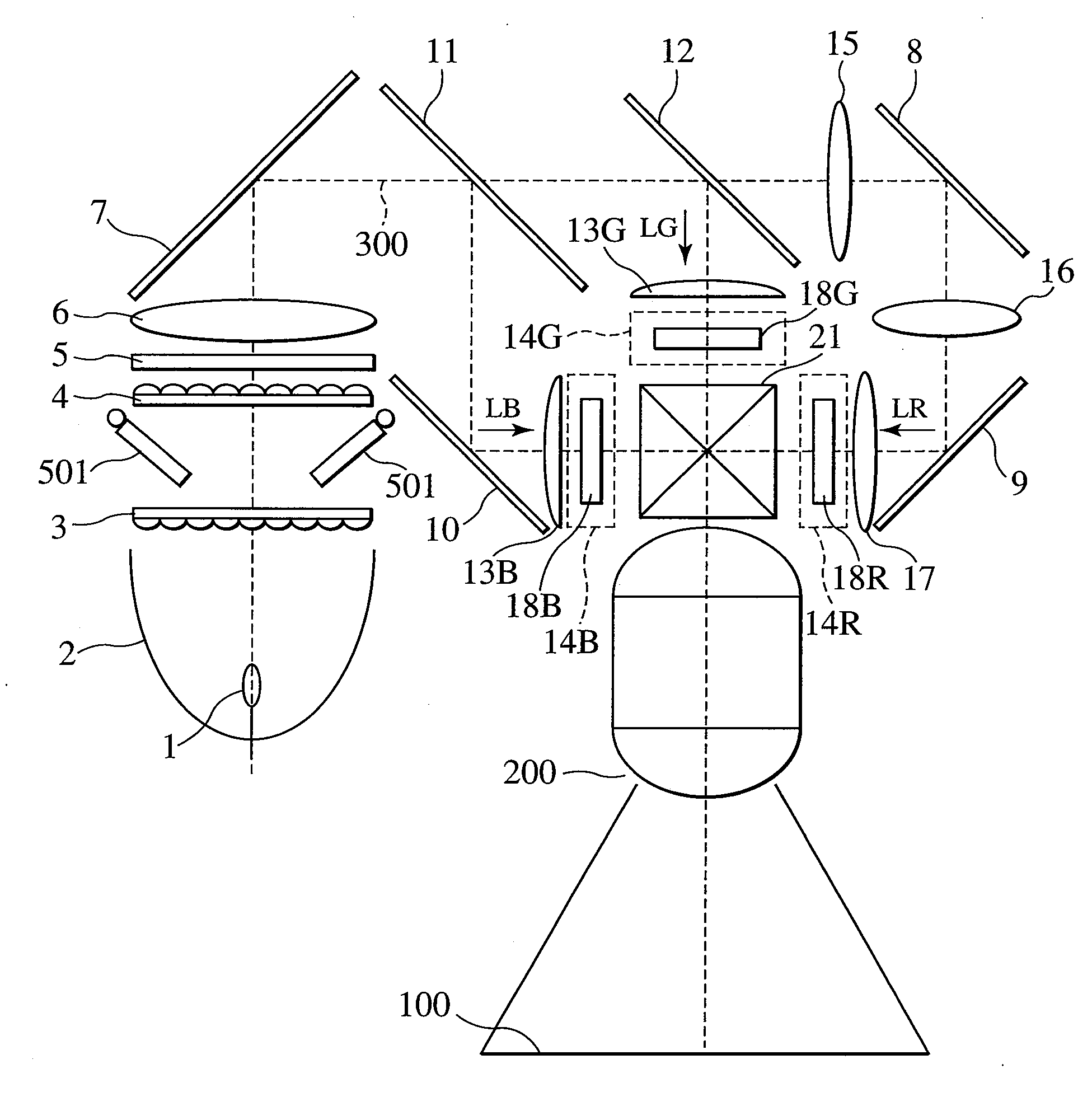
[0005]To widen the dynamic range of a projection type image display apparatus, it is necessary to increase the amount of light masking by a light-masking unit arranged in an illumination optical system. To increase the amount of light masking by the light-masking unit, it is necessary to increase the light-masking section with which light-masking plates included in the light-masking unit mask light beams.
[0007]In particular, the image display element, like a liquid crystal display element, has such a characteristic that degrades more the contrast performance with increasing angle of the incident light with respect to the normal line of the element surface. The above-mentioned problems stand out, if light masking is performed starting from pieces of light having a larger angle with respect to the normal line of an image display element, which adversely affects the contrast performance of the image display element, in order to improve the contrast performance of the projection type image display apparatus.
[0008]An object of the present invention is to enable control of a large amount of light masking through a light-masking unit while maintaining a uniform illumination distribution in an area to be illuminated by the illumination light.
[0009]Another object of the present invention is to provide a projection type display apparatus having a wide dynamic range, excellent power of image expression, and the ability to respond the environment and user's intention.

Problems solved by technology

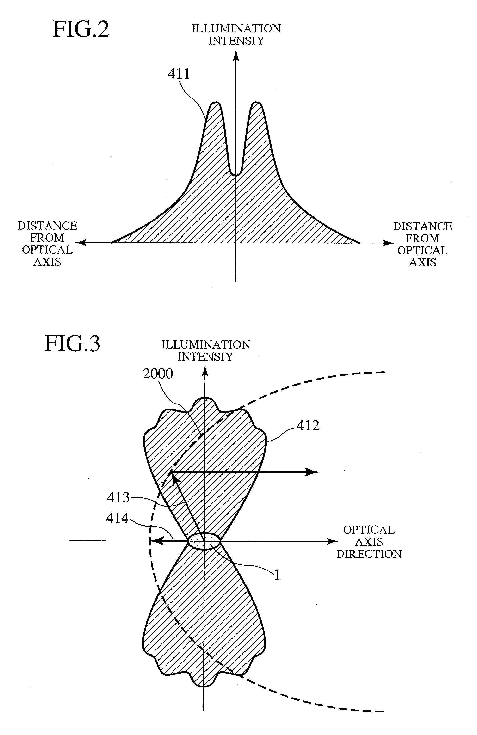
However, there has been a problem that, with the increase in the amount of light masking, the illumination distribution in an area to be illuminated by illumination light is likely to become nonuniform because of a decrease in the number of second light source images superimposed on an area to be illuminated by an illumination optical system formed by array lenses.
There has been another problem that, when the light-masking unit turns or moves a light mask to perform light masking, the variation of the illumination distribution when the light mask is moved or turned is likely to be reflected on a screen.
In particular, the image display element, like a liquid crystal display element, has such a characteristic that degrades more the contrast performance with increasing angle of the incident light with respect to the normal line of the element surface.
The above-mentioned problems stand out, if light masking is performed starting from pieces of light having a larger angle with respect to the normal line of an image display element, which adversely affects the contrast performance of the image display element, in order to improve the contrast performance of the projection type image display apparatus.

Method used


Image

  • Projection type image display apparatus
  • Projection type image display apparatus
  • Projection type image display apparatus

Examples


first embodiment

[0056]With a first embodiment, the light-masking unit is configured such that the light masks 502 and 503 are arranged outside the light beams, as shown in FIG. 8A, to maximize the amount of emitted light and that the units are turned in the directions indicated by arrows 601 and 602 to mask light beams 700 when adjusting the amount of light masking. However, the light-masking unit may be configured such that the light masks 502 and 503 are arranged outside the light beams, as shown in FIG. 8B, to maximize the amount of emitted light and that the units are moved in the direction indicated by arrows 603 and 604 to increase the amount of light masking.

[0057]Furthermore, the light-masking unit may be configured such that they are arranged in parallel with the optical axis in light beams, as shown in FIG. 8C, to maximize the amount of emitted light and that the units are turned in the direction indicated by arrows 605 and 606 to increase the amount of light masking.

[0058]A second embodi...

third embodiment

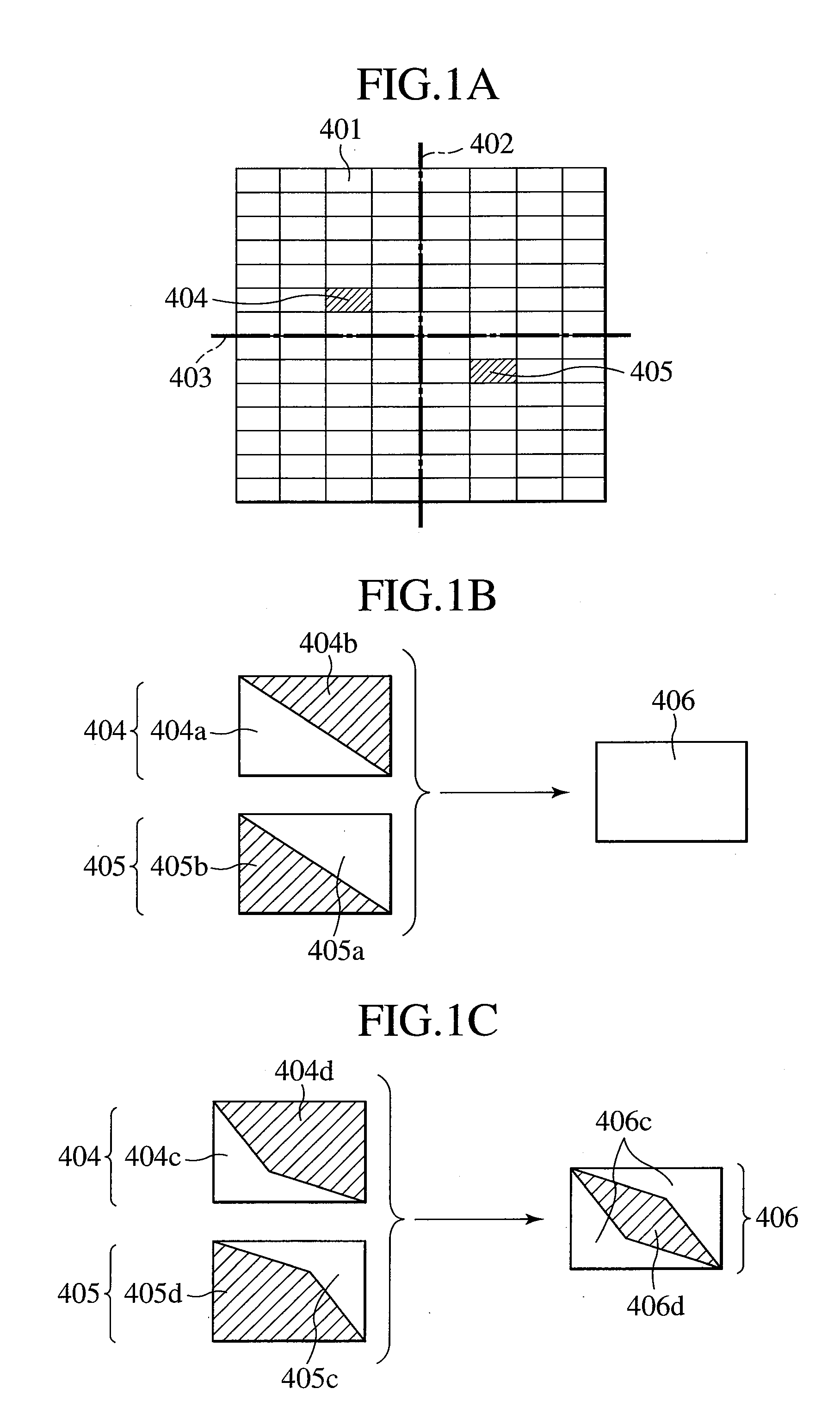
[0065]With a third embodiment, the configuration of the first array lens 3 in FIG. 10A has been modified to the array lens configuration shown in FIG. 10B. Specifically, the array lens is configured such that rectangular cells are arranged, in line symmetry to the two axes which pass through and perpendicularly intersect the optical axis, in even-number columns in terms of one axis and odd-number columns in terms of the other axis. A cell section 421 including the center cells on the array lens in FIG. 10A corresponds to a cell section 545 on the array lens in FIG. 10B. Cell sections 552 on the array lens in FIG. 10A correspond to cell sections 563 or cell sections 567 on the array lens in FIG. 10B. Other cell sections are the same as those in the embodiments in FIG. 5 and FIG. 9. Even if arrangements of even-number columns and odd-number columns are reversed, the same configuration can be made simply by rotating the array lens arrangement shown in FIG. 10B by 90 degrees.

[0066]With ...


PUM


Abstract

According to the present invention, a projection type image display apparatus enables control of a large amount of light masking through a light-masking unit while maintaining a uniform illumination distribution in an area to be illuminated by the illumination light. The apparatus uses two array lenses on which lens cells are arranged in matrix form, where light-masking unit masks the array lens installed on the light source side in their particular area. The light-masking unit adjusts the amount of light emitted from the light source. The light-masking area of lens cells adjacent to lens cells closest to an optical axis is made smaller than the light-masking area of other cells.

Description

CLAIM OF PRIORITY[0001]The present application claims priority from Japanese application serial no. JP 2005-230230, filed on Aug. 9, 2005, the content of which is hereby incorporated by reference into this application.BACKGROUND OF THE INVENTION[0002]The present invention relates to a projection type image display apparatus which forms an optical image based on a picture signal by means of an image display element and projects the optical image on a screen or the like.[0003]With a conventional projector optical system, when optical modulation of the image display element is performed in order to minimize the luminance, a phenomenon called “grayish black” occurs with which the light absorbed by a light-exiting polarization plate is not sufficient and the screen luminance does not decrease. The light-exiting polarization plate aligns the polarization of light beams modulated by the image display element.[0004]For this reason, there is a means for improving the contrast by reducing the...

Claims


Application Information

Patent Timeline
Patent Type & Authority Applications(United States)
IPC IPC(8): G03B21/14
CPCG03B21/208G03B21/14G03B21/28G03B21/20G03B21/2053H04N9/3155H04N9/315H04N9/3152
Inventor SHIMIZU, TAKUYAKATO, KENTARO
Owner MAXELL HLDG LTD
Why Eureka
Try Eureka