
Display device and display method

Active Publication Date: 2010-09-30
SATURN LICENSING LLC
View PDF18 Cites 21 Cited by
  • Summary
  • Abstract
  • Description
  • Claims
  • Application Information

AI Technical Summary

Benefits of technology

[0021]According to the present invention described above, it is possible to provide a novel and improved display device and display method that are capable of improving crossta

Problems solved by technology

However, because the shutters of the shutter glasses are opened together at

Method used


Image

  • Display device and display method
  • Display device and display method
  • Display device and display method

Examples


Example

[0038]Hereinafter, preferred embodiments of the present invention will be described in detail with reference to the appended drawings. Note that, in this specification and the appended drawings, structural elements that have substantially the same function and structure are denoted with the same reference numerals, and repeated explanation of these structural elements is omitted.

[0039]An exemplary embodiment of the present invention will be described in detail in the following order.

[0040]1. Embodiment of present invention

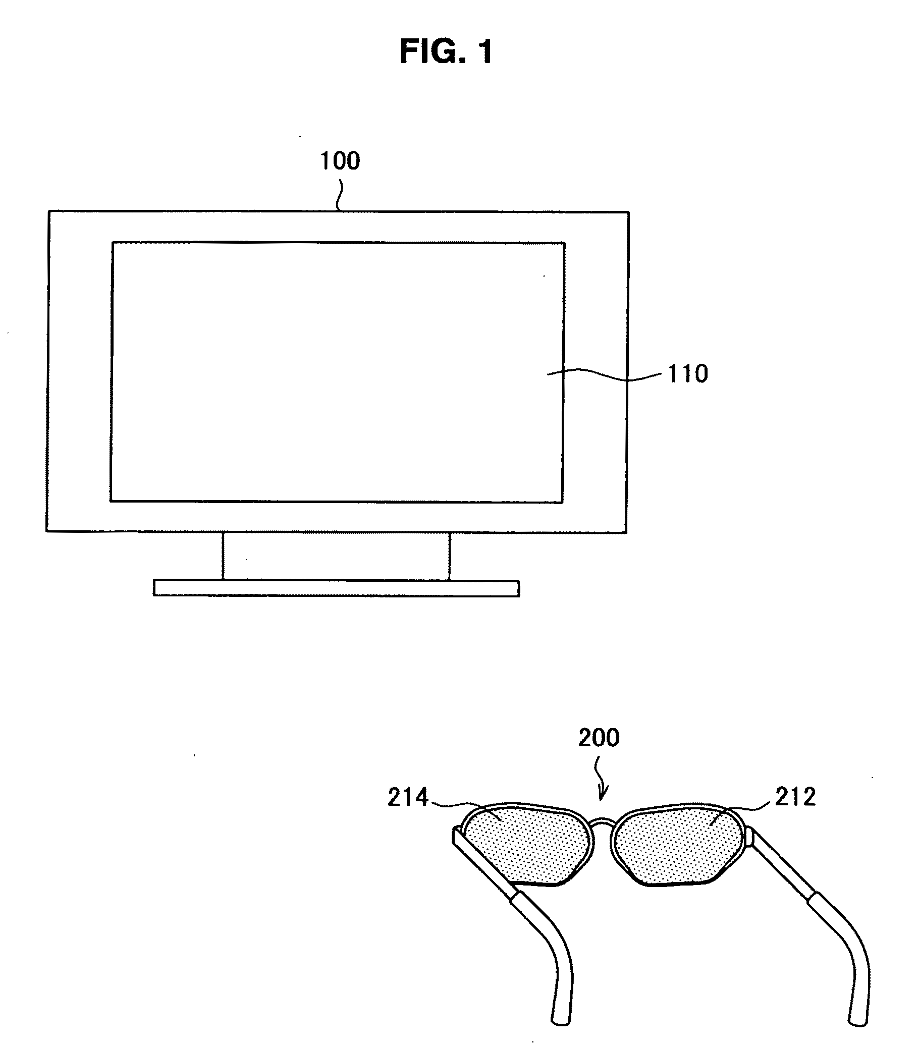
[0041]1-1. Structure of display device according to embodiment of present invention

[0042]1-2. Functional structure of display device according to embodiment of present invention

[0043]1-3. Structure of timing control portion

[0044]1-4. Known technique and problems thereof

[0045]1-5. Drive compensation method

[0046]1-6. Modified examples of drive compensation method

[0047]2. Conclusion

1. EMBODIMENT OF PRESENT INVENTION

1-1. Structure of Display Device According to Embodim...


PUM


Abstract

There is provided a display device that includes a display portion and a drive compensation portion. The display portion line-sequentially displays, in an image display region, a first image based on a first image signal and a second image based on a second image signal, by sequentially switching the first image and the second image at a predetermined interval. The drive compensation portion performs predetermined drive compensation on the first image signal and the second image signal input to the display portion, in accordance with a position of the image display region, a luminance of the first image and a luminance of the second image. The predetermined drive compensation is performed such that an average luminance of the first image or the second image becomes substantially uniform in the image display region during a predetermined period that is shorter than the predetermined interval.

Description

BACKGROUND OF THE INVENTION[0001]1. Field of the Invention[0002]The present invention relates to a display device and a display method.[0003]2. Description of the Related Art[0004]Display devices exist in which an image displayed on a screen is perceived by a viewer as a stereoscopic image. A time sharing display system is known as a technique to cause the viewer to perceive an image displayed on this type of display device as a stereoscopic image. The time sharing display system alternately displays an image for the left eye and an image for the right eye on the entire screen at very short intervals (refer to Japanese Patent Application Publication No. JP-A-9-138384, Japanese Patent Application Publication No. JP-A-2000-36969 and Japanese Patent Application Publication No. JP-A-2003-45343).[0005]An image displayed by the time sharing display system can be perceived by the viewer as a stereoscopic image through shutter glasses worn by the viewer. During an interval in which an image...

Claims


Application Information

Patent Timeline
IPC IPC(8): G09G5/10G09G3/20G09G3/36
CPCG09G3/003G09G3/3611H04N13/0497G09G2340/16H04N13/0438G09G2320/0285H04N13/398H04N13/341
Inventor NAKAHATA, YUJINAKAGAWA, MAKOTO
Owner SATURN LICENSING LLC
Learn More