
Method of driving a display apparatus

a display apparatus and display technology, applied in the field of driving a display apparatus, can solve the problems of reduced total brightness, reduced power consumption, saturated or distorted colors, etc., and achieve the effect of enhancing the display quality of an imag

Inactive Publication Date: 2010-09-30
SAMSUNG DISPLAY CO LTD
View PDF12 Cites 41 Cited by
  • Summary
  • Abstract
  • Description
  • Claims
  • Application Information

AI Technical Summary

Benefits of technology

[0012]Example embodiments of the present invention provide a method of driving a display apparatus capable of enhancing display quality.
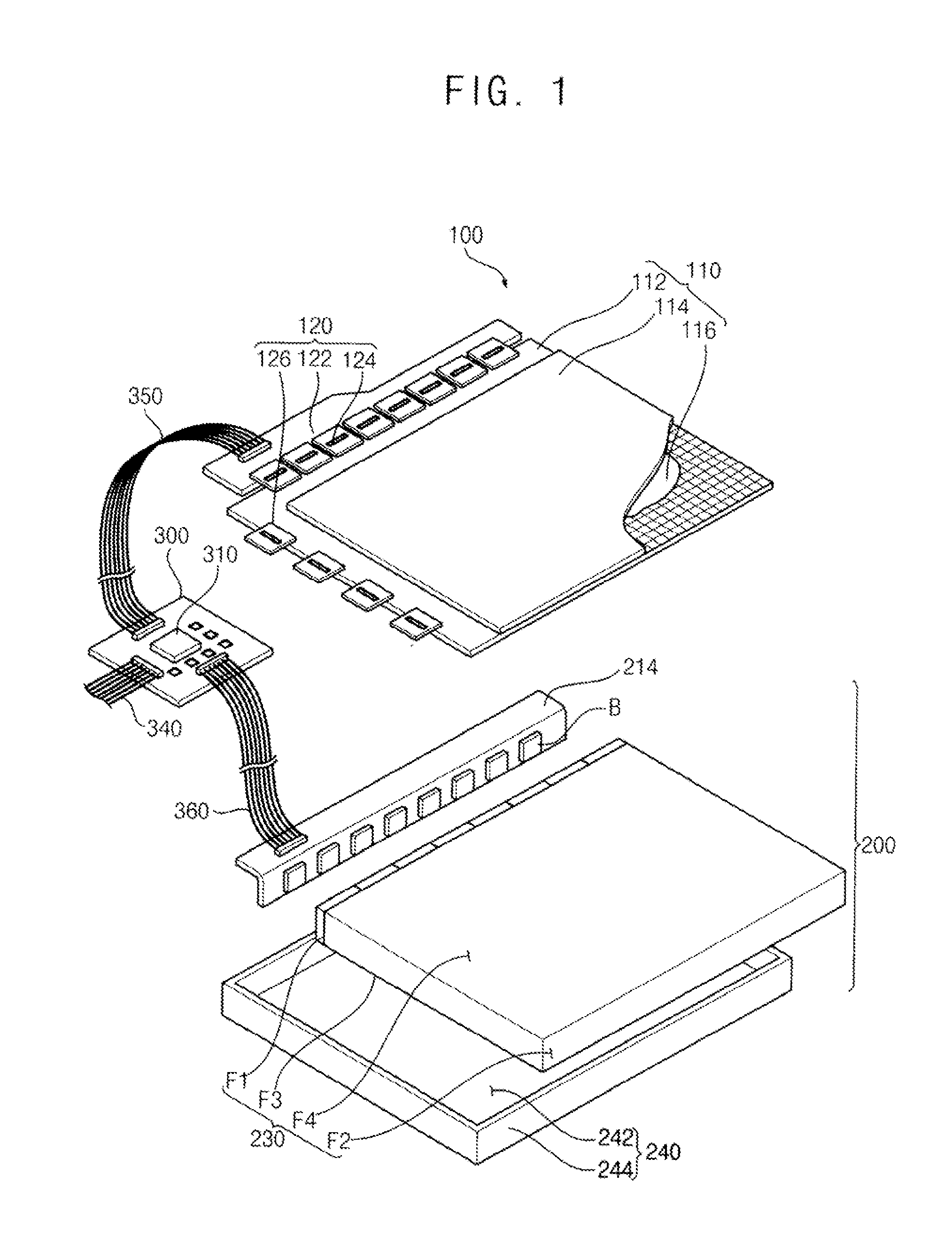
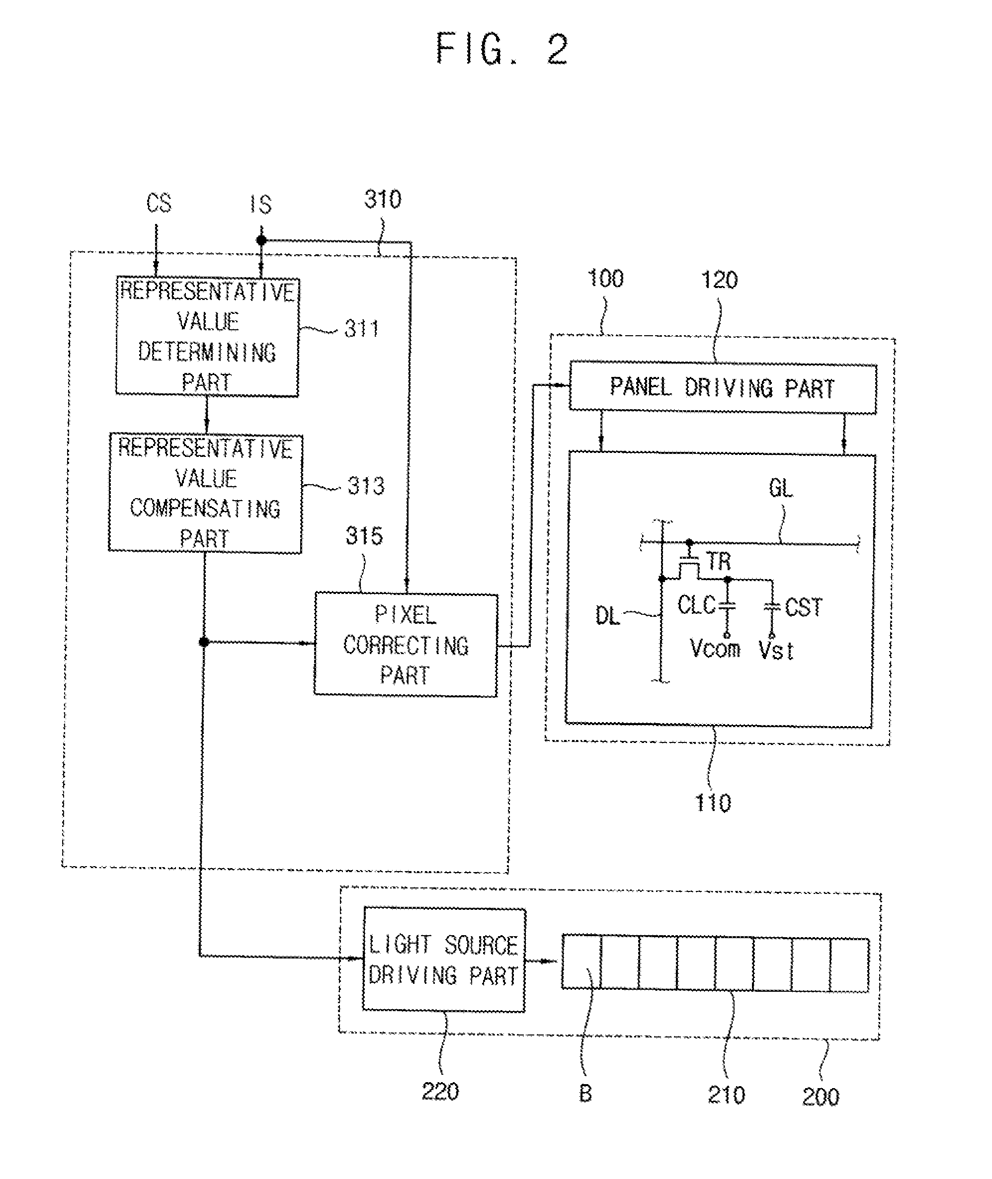
[0027]According to some example embodiments of the present invention, pixel data is compensated by applying a distance weight value at a boundary area of a unit light-emitting block based on a luminance compensation value in which a luminance representative value of a unit light-emitting block is temporary and spatially compensated, so that a phenomenon in which a boundary of the unit light-emitting block is visible is removed. Thus, the display quality of an image may be enhanced.

Problems solved by technology

However, the local dimming driving method may have disadvantages in that total brightness is decreased, a dark object displayed on a screen may not be visible, etc.
However, colors may be saturated or distorted.
Moreover, since the local dimming driving method is used to control the brightness of blocks, power consumption is decreased.
However, the local dimming driving method includes driving per block, so that display quality deterioration and flicker may be generated and a boundary between blocks may be visible.

Method used


Image

  • Method of driving a display apparatus
  • Method of driving a display apparatus
  • Method of driving a display apparatus

Examples


Embodiment Construction

[0040]Embodiments of the present invention are described more fully hereinafter with reference to the accompanying drawings, in which example embodiments of the present invention are shown. Example embodiments of the present invention may, however, be embodied in many different forms and should not be construed as limited to the example embodiments set forth herein. Rather, these example embodiments are provided so that this disclosure will be thorough and complete, and will fully convey the scope of the present invention to those skilled in the art. In the drawings, the sizes and relative sizes of layers and regions may be exaggerated for clarity.

[0041]It will be understood that when an element or layer is referred to as being “on,”“connected to” or “coupled to” another element or layer, it can be directly on, connected or coupled to the other element or layer or intervening elements or layers may be present. In contrast, when an element is referred to as being “directly on,”“direc...


PUM


Abstract

A method for driving a display apparatus, according to one or more embodiments of the present invention, provides a luminance representative value of a unit light-emitting block that may be determined from an external image signal of a plurality of image blocks corresponding to the unit light-emitting block including a plurality of light sources. A luminance compensation value of the unit light-emitting block may be calculated by compensating the luminance representative value. Pixel data of the external image signal in a central area of the unit light-emitting block and a boundary area may be corrected based on the luminance compensation value. A driving signal may be provided to the unit light-emitting block based on the luminance compensation value. Accordingly, a phenomenon in which a boundary of the unit light-emitting block is visible is removed so that the display quality of all image may be enhanced.

Description

RELATED APPLICATIONS[0001]This application claims priority to and benefit of Korean Patent Application No. 2009-0024794, filed on Mar. 24, 2009, in the Korean Intellectual Property Office (KIPO), the contents of which are herein incorporated by reference in their entirety.BACKGROUND[0002]1. Technical Field[0003]Example embodiments of the present invention relate to a method of driving a display apparatus, and in particular, example embodiments of the present invention relate to a method of driving a display apparatus for enhancing display quality.[0004]2. Related Art[0005]Generally, liquid crystal display (LCD) devices include an LCD panel that displays images using light transmittance of liquid crystal molecules and a backlight assembly disposed below the LCD panel to provide the LCD panel with light.[0006]The backlight assembly includes a light source generating light required to display an image on the LCD panel. The light source includes a cold cathode fluorescent lamp (CCFL), a...

Claims


Application Information

Patent Timeline
IPC IPC(8): G09G5/10
CPCG09G3/342G09G3/3611G09G2310/066G09G2360/16G09G2320/0247G09G2320/0646G09G2340/16G09G2320/0233G02F1/133G09G3/20G09G3/36
Inventor CHOE, WEON-JUNKIM, KYOUNG-PHILJANG, DAE-GWANG
Owner SAMSUNG DISPLAY CO LTD
Learn More