
Thermal overload relay

a relay and thermal overload technology, applied in relays, circuit-breaking switches, protective switch details, etc., can solve the problems of reducing the size requiring a large space, etc., and achieve the reduction of the space for placing the contacts in the case, the number of parts of the thermal overload relay, and the effect of reducing the space for storing contacts

Active Publication Date: 2010-09-30
FUJI ELECTRIC FA COMPONENTS & SYST CO LTD
View PDF62 Cites 6 Cited by
  • Summary
  • Abstract
  • Description
  • Claims
  • Application Information

AI Technical Summary

Benefits of technology

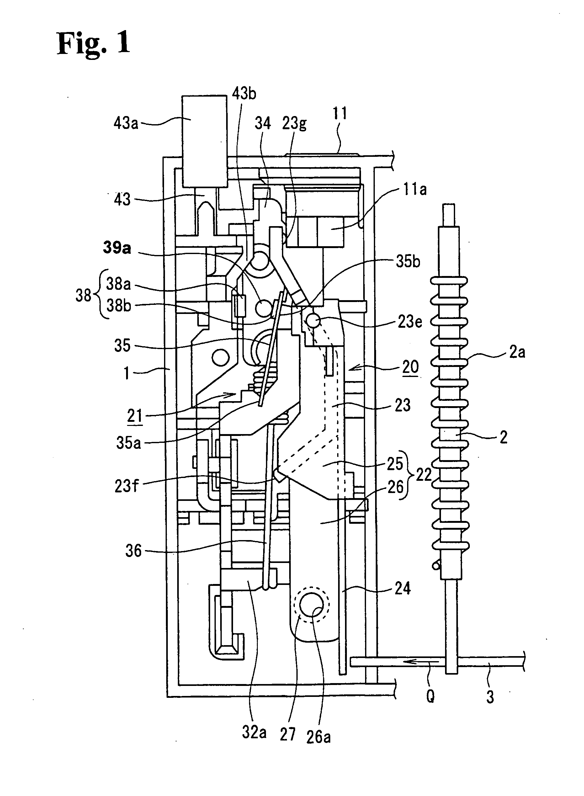
[0015]According to the above-stated invention, the normally opened contact and the normally closed contact are changed-over by rotation of the interlock plate. These contacts are disposed in the vicinity of the front surface and the back surface of the interlock plate. Therefore, a space for placing the contacts in this case is significantly reduced as compared with the conventional device, thereby minimizing a size of the thermal overload relay.
[0016]According to the above-stated invention, even if external disturbances such as vibration and shock occur, the movable contact piece of the contacts in a closed state effectively never separates from the fixed contact piece, thereby avoiding an improper operation of the contacts.
[0018]According to this invention, the number of parts of the thermal overload relay is reduced, and a space for disposition of the contacts is further reduced in this case.
[0019]In a thermal overload relay according to the present invention, the normally opened contact and the normally closed contact are changed-over by rotation of the interlock plate and are disposed in the vicinity of the front surface and the back surface of the interlock plate. Therefore, a space for placing the contacts in the case is significantly reduced as compared with the conventional device, thereby minimizing the size of the thermal overload relay.

Problems solved by technology

Therefore, a large space is required in, the insulator case 1, which is a problem in that it hinders a size reduction of a thermal overload relay.

Method used


Image

  • Thermal overload relay
  • Thermal overload relay
  • Thermal overload relay

Examples


Embodiment Construction

[0026]The following describes the best mode of preferred examples of embodiments of the invention in detail with reference to the accompanying drawings. The parts of the embodiment of the invention similar to the parts in FIG. 4 are denoted by the same symbols and their description is omitted.

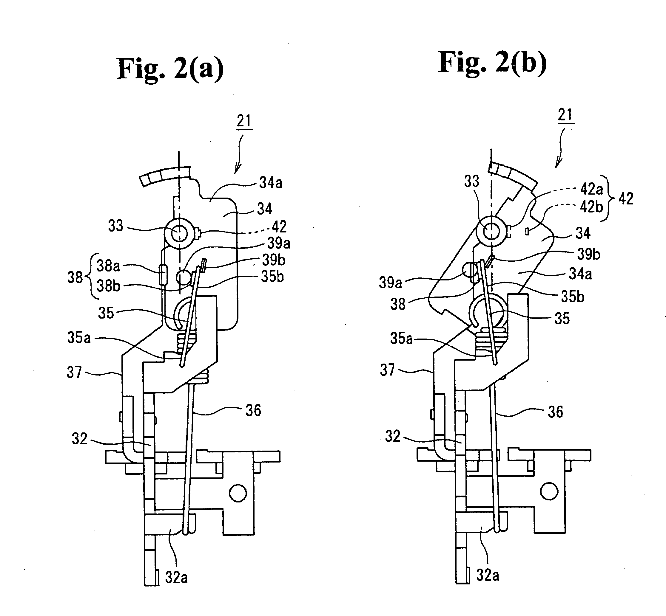
[0027]FIGS. 1 through 3 show an embodiment of a thermal overload relay according to the invention. FIG. 1 is a drawing showing essential parts in a normal state of a thermal overload relay according to the present invention; FIG. 2(a) is a drawing showing the contact reversing mechanism including a normally opened contact (a-contact) in the normal state; FIG. 2(b) is a drawing showing the contact reversing mechanism including the normally opened contact (a-contact) in a tripped state; FIG. 3(a) is a drawing showing the contact reversing mechanism including a normally closed contact (b-contact) in the normal state; and FIG. 3(b) is a drawing showing the contact reversing mechanism including the ...


PUM


Abstract

A thermal overload relay includes main bimetals which bend upon detection of an overload current; a release lever displaced via movement of a shifter moved in response to the bending of the main bimetals; and a contact reversing mechanism for changing-over contacts responsive to a rotation of the release lever. The main bimetals, the release lever and the contact reversing mechanism are all disposed in a case. The contact reversing mechanism includes a pivotable movable plate; a reversing spring reversing the movable plate by coupling with a rotated release lever; and an interlock plate rotating around a support shaft together with the movable plate. Each contact has a normally opened contact piece and a normally closed contact piece and is disposed respectively in the vicinity of a front surface and in the vicinity of a back surface of the interlock plate.

Description

BACKGROUND OF THE INVENTION AND RELATED ART STATEMENT[0001]The present invention relates to a thermal overload relay for change-over of a contact upon detection of an overcurrent.[0002]Patent Document 1, for example, discloses a thermal overload relay operated by detecting an overcurrent running in the main circuit.[0003]The thermal overload relay of Patent Document 1 is described referring to FIG. 4.[0004]This thermal overload relay comprises, in an insulator case 1 made of a resin mould, main bimetals 2 inserted in three phase electric circuit and wound with heaters 2a, a shifter 3 linked to free ends of the main bimetals 2 and movably supported on the insulator case 1, a switching mechanism 4 disposed in the insulator case 1 allowing linking to an end of the shifter 3, and a contact reversing mechanism 5 to changeover contacts by operation of the switching mechanism 4.[0005]The switching mechanism 4 comprises a temperature compensation bimetal 7 linked to one end of the shifter 3...

Claims


Application Information

Patent Timeline
Patent Type & Authority Applications(United States)
IPC IPC(8): H01H61/01
CPCH01H83/223H01H71/1054H01H71/7445H01H71/162
Inventor FURUHATA, YUKINARIMORISHITA, FUMIHIROKAMOSAKI, TAKEO
Owner FUJI ELECTRIC FA COMPONENTS & SYST CO LTD
Learn More