Trailing arm type suspension

a technology of suspension and railing, which is applied in the direction of resilient suspension, interconnection system, vehicle components, etc., can solve the problems of difficult to improve the handling (driving stability) and the response (driving response) of an automobile, and achieve the effect of increasing the rigidity of the installation of the suspension member to the side member, regulating more reliably, and increasing the rigidity of the vehicle body

Active Publication Date: 2010-09-30
SUZUKI MOTOR CORP
View PDF11 Cites 3 Cited by
  • Summary
  • Abstract
  • Description
  • Claims
  • Application Information

AI Technical Summary

Benefits of technology

[0022]The front end portion of the reinforcing bar is disposed in the vehicle front side of the front end portion of the trailing arm. Therefore, the reinforcing bar can be disposed in a wider range in the vehicle longitudinal direction relative to the trailing arm, so that the movement of the trailing arm to the fuel tank side, can be regulated more reliably by the reinforcing bar.
[0023]Furthermore, the reinforcing bar is disposed in the substantially horizontal direction so as to be continuous from the rear end of a portion of the side member, which extends along the vehicle longitudinal direction, to the side member which relates to this portion. Therefore, an impact load can be transmitted effectively in the vehicle longitudinal direction via the reinforcing bar, so that the rigidity of the vehicle body can be increased.
[0024]The rear end portion of the reinforcing bar is attached to the lower end portion of the mounting bolt. Therefore, the installation rigidity of the suspension member to the side member can be increased. The rigidity of suspension parts attached to the suspension member can be increased. Furthermore, the handling (driving stability) and the response (driving response) of the automobile are improved, and thereby the quality of commodities can be increased.
[0026]if a rubber bush including an internal cylinder and a rubber form an elastic body which is vulcanized and adhered to the outer peripheral surface of the internal cylinder, is pressed into a vertical hole formed in the suspension member; and
[0027]the side member, the internal cylinder, and the rear end portion of the reinforcing bar are connected to one another by the mounting bolt inserted through the internal cylinder so as to install the rear end portion of the reinforcing bar to the lower end portion of the mounting bolt,
[0029]For example, regarding a feature configured merely by pressing the rubber bush including the internal cylinder and the rubber form elastic body which are vulcanized and adhered to the outer peripheral surface of the internal cylinder, into the vertical hole which is formed in the suspension member, and by connecting the side member and the internal cylinder to each other by the mounting bolt which is inserted through the internal cylinder, the mounting bolt may fall down because of an external force applied to the suspension.

Problems solved by technology

Therefore, the installation rigidity of the suspension member, relative to the vehicle body frame, cannot be increased sufficiently, so that it has been difficult to improve the handling (driving stability) and the response (driving response) of an automobile.

Method used


Image

  • Trailing arm type suspension
  • Trailing arm type suspension
  • Trailing arm type suspension

Examples


Embodiment Construction

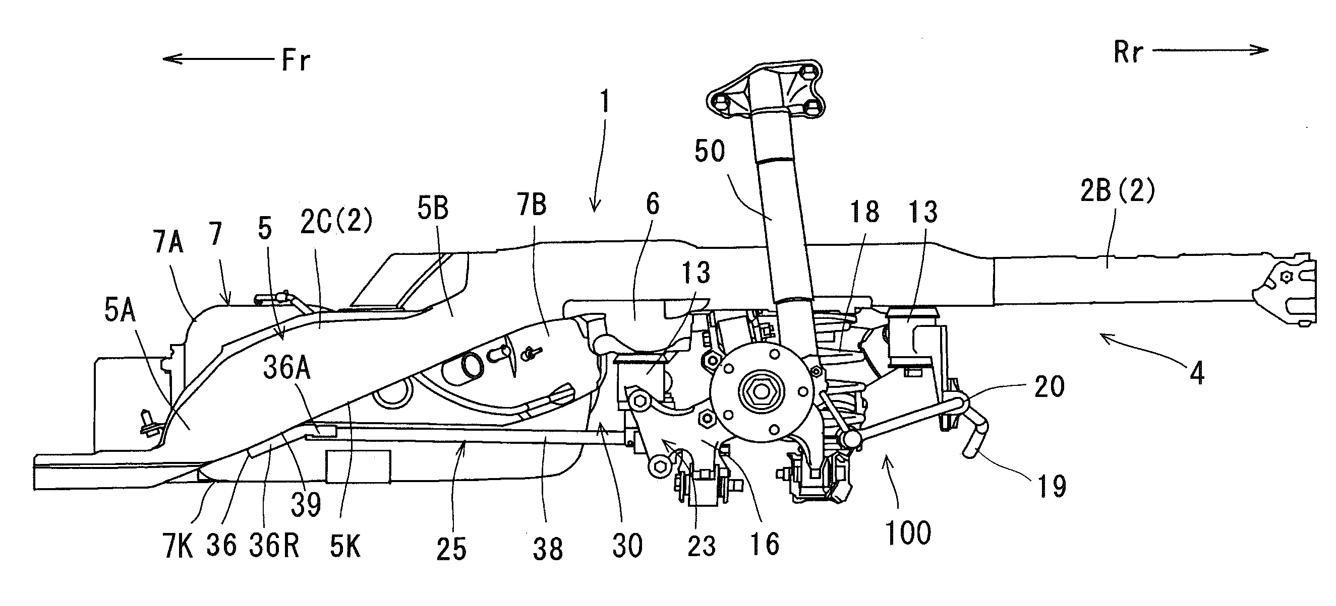
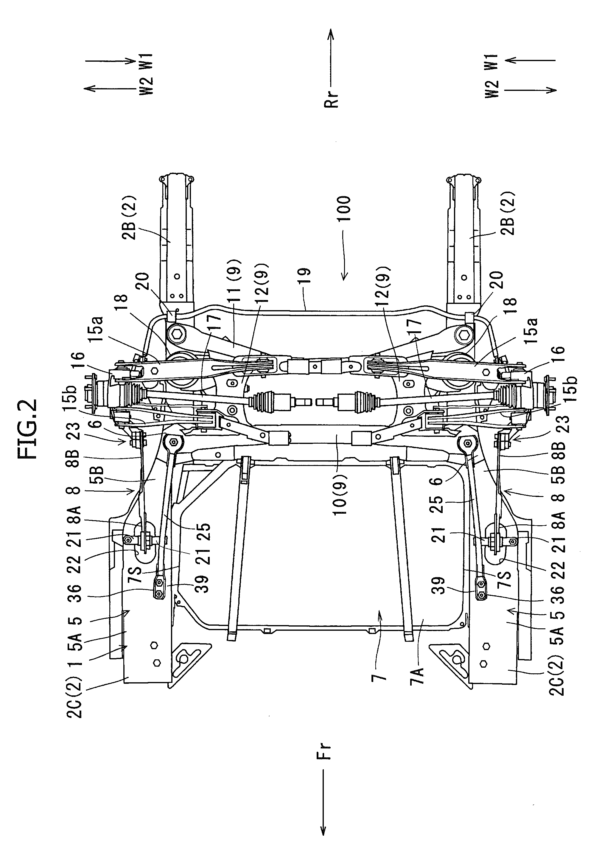
[0050]An embodiment of the present invention will now be described with reference to the accompanying drawings.

Feature of Vehicle Body Frame 1

[0051]FIGS. 1 to 3 show a trailing arm type suspension of an automobile. As shown in FIGS. 1 to 3, a vehicle body frame 1 includes a pair of right and left side members 2 extending along the vehicle longitudinal direction, and a plurality of cross members installed between the side members 2. The side members 2 and the cross members are disposed under a floor 4 of the lower part of a floor panel, and are formed so as to have a longitudinal cross section of a hat shape which has the opened upper side. A pair of right and left flanges in the upper end portion of each of the side members 2 and the cross members are welded to the lower surface of the floor panel.

[0052]A longitudinal intermediate portion 2C (in particular, a portion located from a rear wheel toward the vehicle front side Fr in a vehicle rear half part of the side member 2) of the s...


PUM


Abstract

A trailing arm type suspension improves the handling (driving stability) and the response (driving response) of an automobile by increasing the installation rigidity of a suspension member to a vehicle body frame. In the trailing arm type suspension including a pair of right and left trailing arms which extend in the vehicle longitudinal direction, a reinforcing bar for connecting a suspension member in the vehicle rear side of the trailing arm to a connecting part of a vehicle body frame in the vehicle front side of the suspension member, is disposed between a fuel tank and the trailing arm, and the reinforcing bar and the trailing arm overlap each other as viewed from the side of the vehicle.

Description

FIELD OF THE INVENTION[0001]The present invention relates to a trailing arm type suspension including a pair of right and left trailing arms which extend along the vehicle longitudinal direction.BACKGROUND OF THE INVENTION[0002]Conventionally, in trailing arm suspensions of the above-described type, as described in Japanese Examined Utility Model Application Publication No. 7-50268, a suspension member supporting suspension parts, was merely been installed between right and left side members of a vehicle body frame, which extend in the vehicle longitudinal direction.BRIEF SUMMARY OF THE INVENTION[0003]According to the above-described conventional feature, the suspension member is merely installed between the paired right and left side members of the vehicle body frame, which extend along the vehicle longitudinal direction. Therefore, the installation rigidity of the suspension member, relative to the vehicle body frame, cannot be increased sufficiently, so that it has been difficult...

Claims


Application Information

Patent Timeline
Patent Type & Authority Applications(United States)
IPC IPC(8): B60G3/14
CPCB60G3/285B60G2200/182B60G2206/60B60G2204/15B60G2204/43B60G2200/422
Inventor ONDA, KENICHIOHKUBO, KENSUKE
Owner SUZUKI MOTOR CORP
Why Eureka
Try Eureka