Landing Gear Mechanism for Model Airplane

a technology of model airplanes and landing gears, which is applied in the direction of alighting gears, toys, toy aircraft, etc., can solve the problems of increasing drag, causing the nose of the airplane to hit the ground and stall the engine, and increasing the drag

Inactive Publication Date: 2010-09-30
MCNUTT JERRY L
View PDF12 Cites 5 Cited by
  • Summary
  • Abstract
  • Description
  • Claims
  • Application Information

AI Technical Summary

Problems solved by technology

This can cause the plane to teeter on the wheels and often creates “nose over” conditions during both take-offs and landings.
In a “nose over” condition, the tail of a radio controlled model airplane will rise, and the nose of the airplane will hit the ground and stall the engine.
Most runways are grass, causing increased drag and exacerbating the nose over condition because of the higher rolling resistance.
This can be dangerous, as the model airplane may be somewhat uncontrollable for the first few seconds of flight.
This type of take-off also looks unnatural.
No commercially satisfactory design has been made to adequately retract landing gear having forwardly angled struts.

Method used


Image

  • Landing Gear Mechanism for Model Airplane
  • Landing Gear Mechanism for Model Airplane
  • Landing Gear Mechanism for Model Airplane

Examples


Embodiment Construction

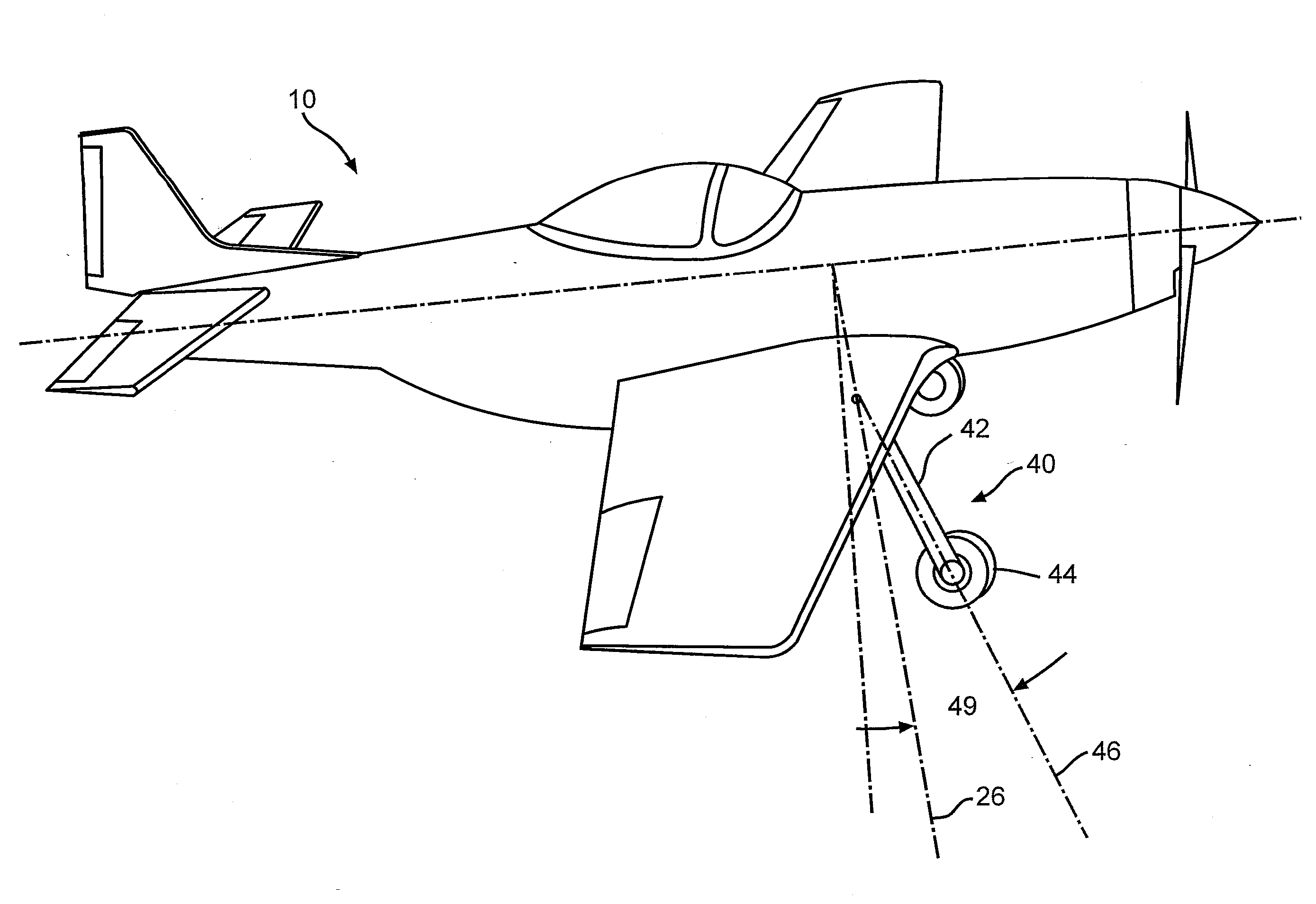
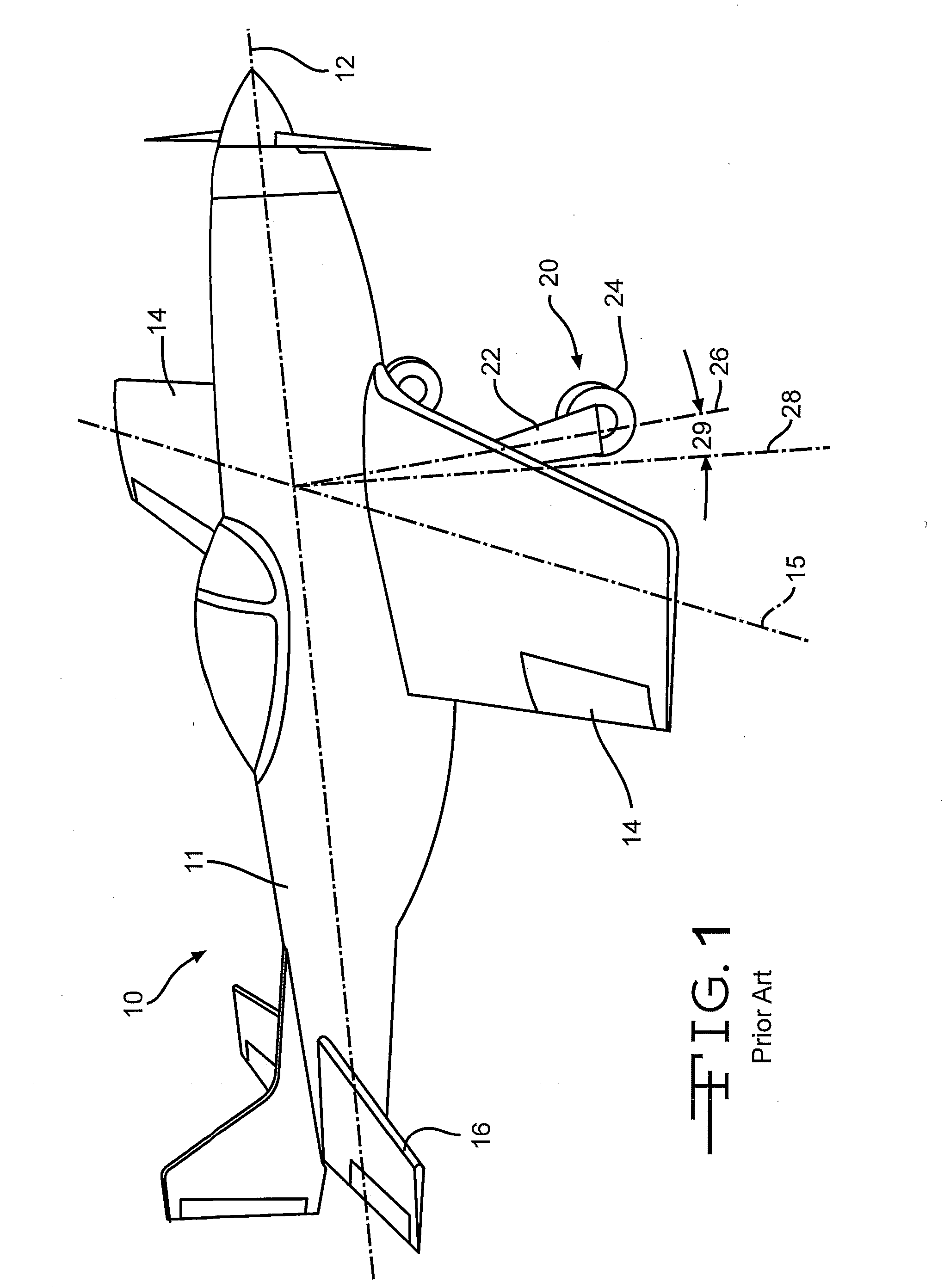
[0018]Referring to FIG. 1, a radio controlled model airplane 10 has a fuselage 11 with a longitudinal central axis 12. Wings 14 extend transversely to the fuselage, generally along an axis 15. Airplane 10 is a “tail-dragger”, having a small fixed rear landing wheel 16 is attached to the rear portion of the fuselage. However, this invention may also be suitable for other airplane types, such as a “tri-gear” type having two wheels generally under the wings and third wheel under the nose of the aircraft. Landing gear 20 is attached to the underside of each wing. Each landing gear includes a strut 22 and a wheel 24 rotatably attached to each strut. Strut 22 lies on a vertical axis 26 witch in most prior art designs is substantially perpendicular to fuselage axis 12. The embodiment shown in FIG. 1 has struts which are tilted slightly forward relative to an axis 28 perpendicular to the fuselage axis 12. Generally, the forward tilt angle 29 of a retractable landing gear is in the range of ...


PUM


Abstract

A radio controlled model airplane has landing gear including a wheel rotatably mounted on a strut. The wheel and strut are retractable into the airplane wing. The strut is angled forwardly relative to the wing surface where the strut is attached such that the wheel is forward of the airplane center of gravity just prior to takeoff and touchdown. The landing gear includes a control assembly mounted on the wing. The control assembly includes a housing and a pivot pin on which the strut is mounted. The pivot pin is rotatable and pivotable around one of its ends. The control assembly also includes a cam which causes the pivot pin to pivot upon rotation, thereby causing the strut to move through a plane oblique to the wing.

Description

CROSS-REFERENCE TO RELATED APPLICATION[0001]This application claims the benefit of U.S. Provisional Application No. 61 / 165,208 filed Mar. 31, 2009, the disclosure of which is incorporated herein by reference.BACKGROUND OF THE INVENTION[0002]This invention relates in general to landing gear for radio controlled model airplanes, and more particularly to an improved structure for retractable landing gear.[0003]Most radio controlled model airplanes are equipped with landing gear to facilitate take-offs and landings. Typically, the landing gear includes a wheel supported on the end of a strut. Generally, the landing gear struts are perpendicular to the airplane wings to which they are attached. Some landing gear is permanently fixed in position. Other landing gear is retractable and folds up into the wing after take off. Retractable landing gear is desirable in many types of radio controlled airplanes for reasons such as authenticity, maneuverability and handling.[0004]The center of grav...

Claims


Application Information

Patent Timeline
Patent Type & Authority Applications(United States)
IPC IPC(8): A63H27/32
CPCA63H27/02
Inventor MCNUTT, JERRY L.
Owner MCNUTT JERRY L
Why Eureka
Try Eureka