
Modular Air Management Devices

a module-type air management and airflow technology, applied in ventilation systems, electrical apparatus casings/cabinets/drawers, instruments, etc., can solve the problems of increasing the operating range of the inlet temperature of the air drawn into the device, and increasing the failure rate of electronic devices

Inactive Publication Date: 2010-09-23
LINHARES JR MANUEL D +6
View PDF6 Cites 29 Cited by
  • Summary
  • Abstract
  • Description
  • Claims
  • Application Information

AI Technical Summary

Benefits of technology

"The invention provides modular air management devices that can direct or divert air flow within an equipment cabinet or enclosure to address the problem of inadequate cooling of electronic devices that do not implement traditional \"front to back\" breathing methodologies. These devices can be used with non-\"front to back\" breathing electronic devices in a \"front-to-back\" air-distributed enclosure, and can be adapted for reversible application, adjustable application, and hot swappability. The devices can be installed in multiple arrangements and configurations, and can be constructed in multiple materials to meet different cost and environment requirements."

Problems solved by technology

The addition of the doors and panels, however, exacerbates the problem of heat removal within the cabinets and enclosures.
However, as more powerful equipment is installed in cabinets, and as the cabinets become more densely packed with electronic equipment, the inlet temperature of the air drawn into the devices is more likely to exceed the recommended operating range of the device.
The result is an upward trend in the failure of these electronic devices.
Such equipment failures are more than an inconvenience, as some failures may result in interruptions to mission critical systems and communications, such as those used for example in emergency response management, aviation and flight control, process control, and finance.
In addition to the disruption to the systems and communications described above, these electronic devices themselves are expensive.
While it may be possible to redesign these devices to conform to the standard “front to back” air flow configuration, this is usually an expensive and impractical undertaking, and typically not under the control of data center managers or those who install and maintain the cabinets and enclosures.

Method used


Image

  • Modular Air Management Devices
  • Modular Air Management Devices
  • Modular Air Management Devices

Examples


Embodiment Construction

Modular Air Management Scoop Assembly

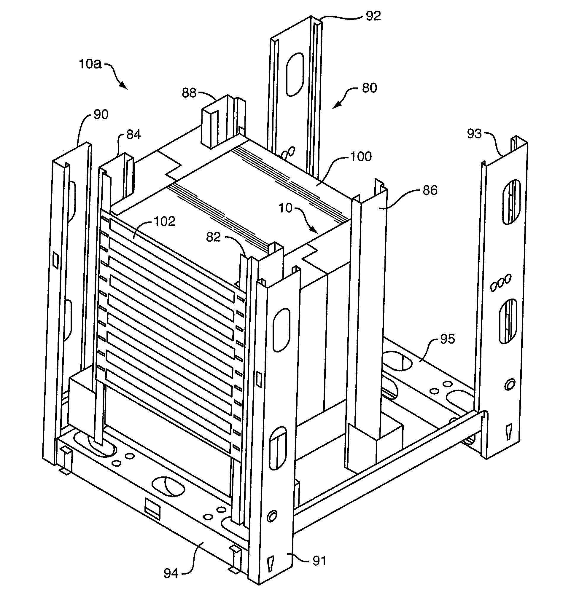
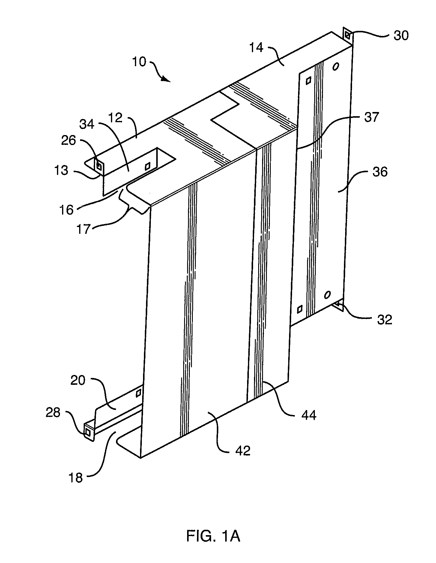
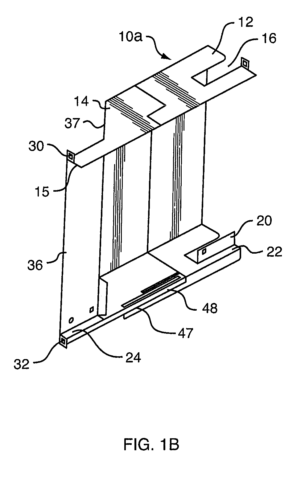
[0058]In a preferred embodiment, and as shown in FIG. 1A, the invention comprises a modular air management scoop assembly 10 for use with a “side to side” breathing electronic device in a “front-to-back” air-distributed enclosure. Air management scoop assembly 10 is designed to be coupled to the rails of an enclosure or cabinet. Air management scoop assembly 10 directs cold air from the front of the enclosure into one side of a “side to side” breathing electronic device, and directs the heated air from the opposite side of the “side to side” breathing electronic device to the back of the enclosure. Air management scoop assembly 10 is adjustable in size and reversible, such that one mechanical structure can be used to both direct air into the electronic device and direct air out of and away from the electronic device. Air management scoop assembly 10 also supports the electronic device within the enclosure, and allows the electronic device to be h...


PUM


Abstract

The invention provides modular air management devices for directing or diverting air flow within an equipment cabinet or enclosure to provide adequate cooling for non-“front to back” breathing electronic devices, and include a scoop assembly, a tray assembly, a vertical mount assembly, and a shroud assembly. The air management devices are designed to direct air flow to and from “side to side” breathing and “side inlet, rear exhaust” electronic equipment. The assemblies may be mounted inside or outside enclosure rails and may be augmented with fan assemblies.

Description

CROSS-REFERENCE TO RELATED APPLICATIONS[0001]This application claims priority to U.S. Provisional Patent Application Ser. No. 61 / 102,912, entitled “Directional Air Scoop,” filed on Oct. 6, 2008, and to U.S. Provisional Patent Application Ser. No. 61 / 098,067, entitled “Directional Air Manager,” filed on Sep. 18, 2008. The entire contents of both priority applications are expressly incorporated by reference herein.FIELD OF THE INVENTION[0002]The invention relates to cabinets and enclosures for rack-mounted electrical and computer equipment, and particularly to assemblies for improving the air flow distribution within such cabinets and enclosures.BACKGROUND OF THE INVENTION[0003]Electronic equipment, such as computer servers and data storage devices, is often mounted on a rack or frame using mounting members such as shelves, rails and / or brackets. Doors and panels are often added to the frames and racks, creating cabinets and enclosures, to protect the electronic equipment from the ext...

Claims


Application Information

Patent Timeline
Patent Type & Authority Applications(United States)
IPC IPC(8): H05K7/20
CPCH05K7/20736
Inventor LINHARES, JR., MANUEL D.TRESH, MICHAELFOLEY, MEAGANLUCIA, DAVIDDIGNUM, MARKMURPHY, DANLATINO, RICHARD
Owner LINHARES JR MANUEL D
Learn More