
Air management system for heavy duty truck under-hood heat control

a technology for air management and heavy duty trucks, which is applied in the direction of roofs, machines/engines, transportation and packaging, etc., can solve the problems of high heat generation of the internal combustion engine of a heavy duty truck, the inefficiency of the fan itself, and the fact that trucks equipped with engines over 250 horsepower (186 kw) have begun to experience severe under-hood heat problems

Active Publication Date: 2008-05-01
ENVIRO COOL INC
View PDF32 Cites 25 Cited by
  • Summary
  • Abstract
  • Description
  • Claims
  • Application Information

AI Technical Summary

Benefits of technology

[0013]Briefly stated, the present invention provides a system for removing heat from the engine compartment of a vehicle by isolating heat from the radiator from the engine compartment (above and to...

Problems solved by technology

The internal combustion engine of a heavy duty truck produces great quantities of heat.
This is caused in part by the natural inefficiency of the fan itself.
Trucks equipped with engines over 250 horsepower (186 kW) have consequently begun to experience severe under-hood heat problems.
The additional heat produced under the hood of a modern heavy duty truck has raised temperatures under the hood to unacceptable levels.
The additional heat and temperature reduce the lives of components in the engine compartment and reduce engine efficiency.
The heat also can transfer into the vehicle operator cab and can make both the air temperature in the cab and surface temperatures on the floor and front wall of the cab uncomfortably high.
Attempts to enlarge the radiator, by repositioning it, tilting it, or splitting it, have not been sufficient.
Enlarging the fan is likewise impractical and would increase the power requirements for running it.
Packing more equipment in the engine compartment further makes airflow more difficult.
These systems are not easily adaptable to the needs of a heavy duty truck.

Method used


Image

  • Air management system for heavy duty truck under-hood heat control
  • Air management system for heavy duty truck under-hood heat control
  • Air management system for heavy duty truck under-hood heat control

Examples


Embodiment Construction

[0029]The following detailed description illustrates the invention by way of example and not by way of limitation. The description clearly enables one skilled in the art to make and use the invention, describes several embodiments, adaptations, variations, alternatives, and uses of the invention, including what is presently believed to be the best mode of carrying out the invention.

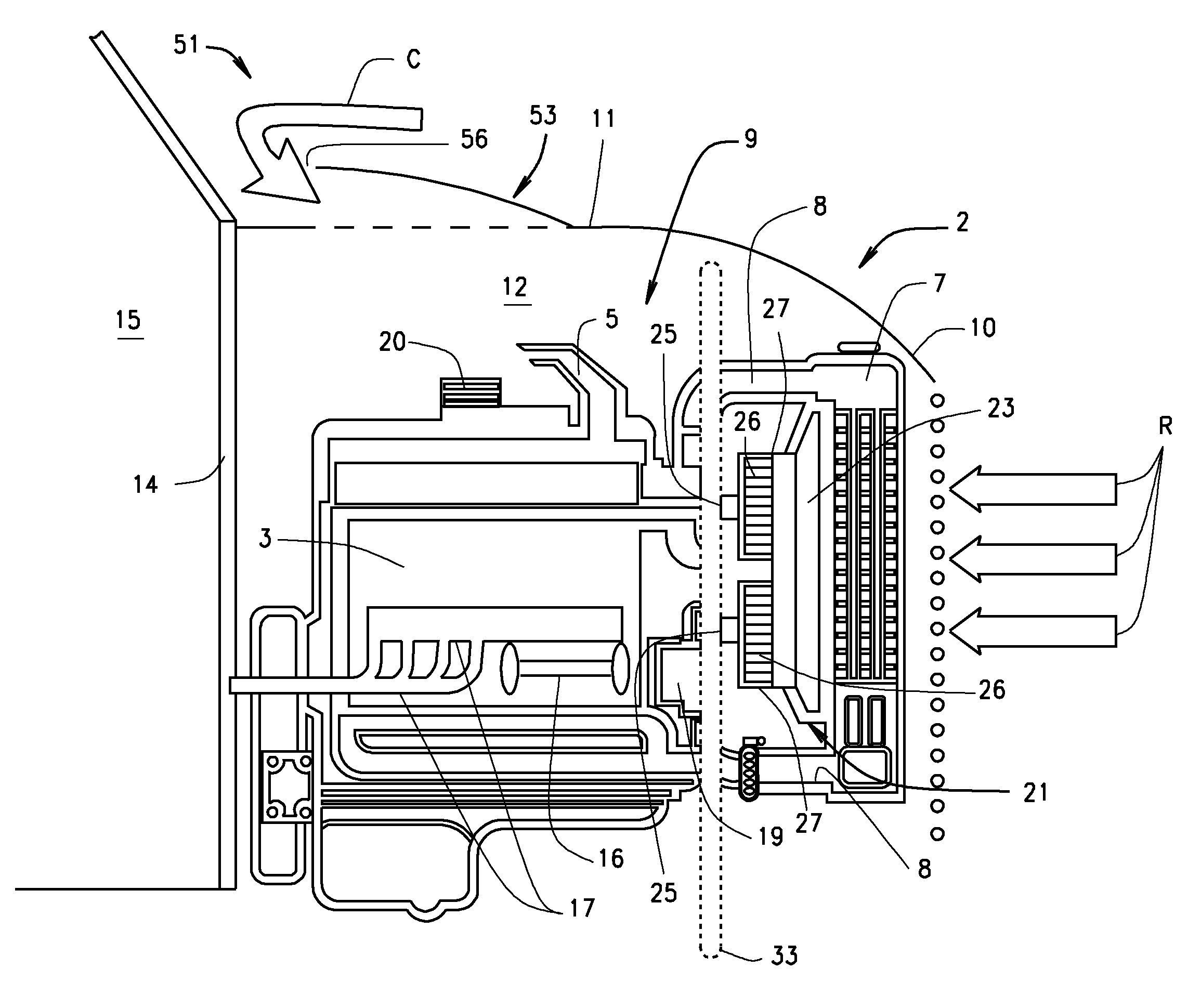
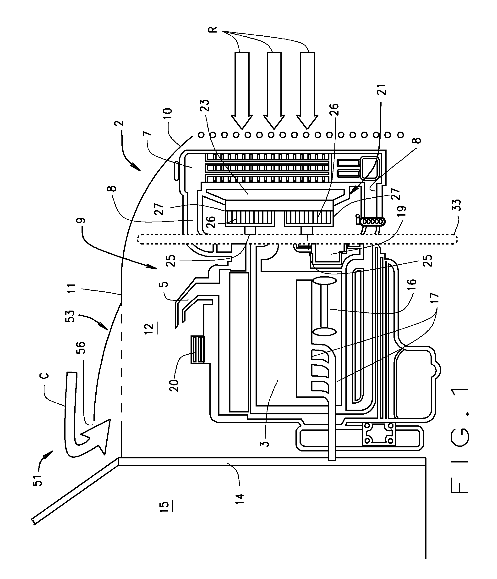
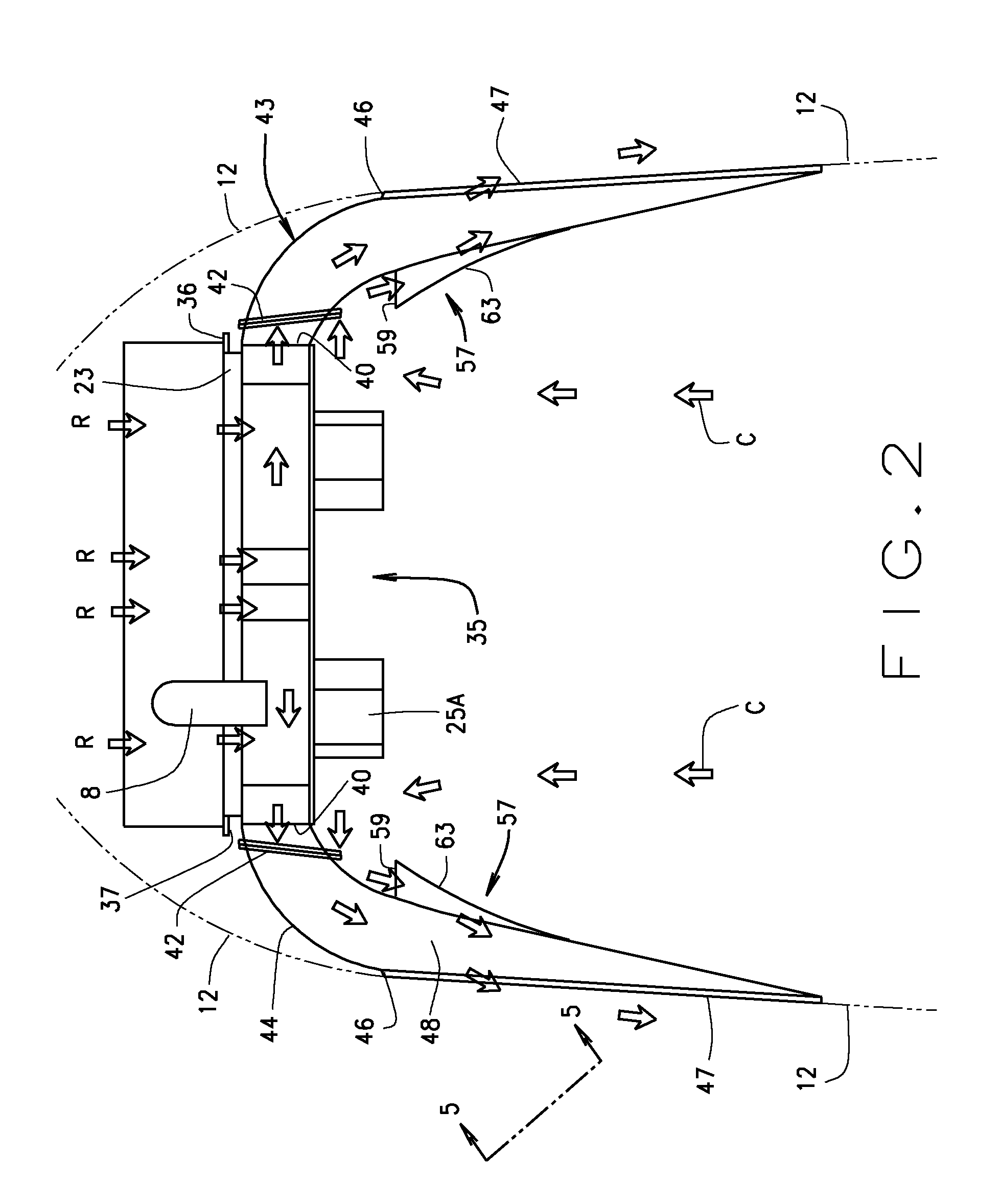
[0030]As shown in the FIGURES, an internal combustion engine in a large heavy duty truck 2 (FIGS. 1 and 8) includes the engine block 3, air intake 5, and a radiator 7 which cools coolant circulated from inside the engine block 3 through passages 8. All of these components of the engine are contained in an engine compartment 9 having a front 10 (usually at or just ahead of the radiator), a top 11, and sides 12. The top and much of the sides are generally formed as a raisable hood 13 (FIG. 8), which is typically hinged to the body of the truck in the area of a lower front end of the truck. At the back of th...


PUM


Abstract

A system for removing heat from the engine compartment (9) of a heavy duty truck. A first ventilating system removes heat from the radiator. It is isolated from a second ventilating system that removes heat from the engine compartment. The first system takes heat from the radiator through a plenum by centrifugal squirrel cage blowers, and is directs it out to ambient by ductwork. The second system draws ambient air generally from back to front of the engine compartment, preferably by cowl induction, without the use of ram air from the vicinity of the radiator. The exits of the two systems are into a slip stream of the heavy duty truck, and the exit of the second ventilating system is into a slip stream of the first, to scavenge air out of the engine compartment.

Description

CROSS-REFERENCE TO RELATED APPLICATIONS[0001]This application is related to and claims the benefit of U.S. Provisional Application 60 / 863,740, filed Oct. 31, 2006, the disclosure of which is hereby incorporated by reference.STATEMENT REGARDING FEDERALLY SPONSORED RESEARCH[0002]Not Applicable.BACKGROUND OF THE INVENTION[0003]This invention relates to systems for reducing temperatures under the hood of a vehicle. It has particular, but not exclusive, application to such systems for use in a heavy duty truck, more particularly to the tractor portion of a tractor-trailer rig. Heavy duty trucks are typically over-the-road and vocational vehicles considered as weight class 4 to 8. Class 4 is generally considered to include vehicles with a gross vehicle weight of 14,001 lb to 16,000 lb (6350 kg to 7257 kg). The invention is particularly useful with weight class 6 to 8 vehicles, most particularly class 7 to 8 vehicles. Class 6 includes vehicles with a gross vehicle weight of 19,501 lb to 26...

Claims


Application Information

Patent Timeline
IPC IPC(8): B60K11/00
CPCB60K11/08B60Y2200/14F01P1/06F01P2001/005F01P11/10B60K11/00B62D25/10B62D25/12B60Y2200/142
Inventor STURMON, GEORGE R.MURRAY, EDWARD M.
Owner ENVIRO COOL INC
Learn More