Optical subassembly implementing sleeve and optical device with transparent resin package

Inactive Publication Date: 2010-09-16
SUMITOMO ELECTRIC IND LTD
View PDF4 Cites 1 Cited by
  • Summary
  • Abstract
  • Description
  • Claims
  • Application Information

AI Technical Summary

Benefits of technology

[0009]One of aspects of the present invention relates to an optical subassembly that comprises an optical device and an optical receptacle. The optical device encloses a semiconductor optical device therein. In an embodiment, the optical device has a resin body transparent to light subject to the semiconductor optical device. The optical receptacle, which may be made of resin, includes a sheath portion with a first bore and a sleeve portion with a second bore. The first bore receives the optical device therein, while, the second bore receives an external optical fiber. The first bore provides at least one rib and the optical device provides a hollow in a position corresponding to the rib and being filled with an ultraviolet cured resin. In the present invention, the rib in the first bore shows an anchor effect for the ultraviolet cured resin filling the hollow in the optical device, which enhances bond strength of the ultraviolet cured resin.
[0010]The optical receptacle provides an aperture at a step between the sheath portion and the sleeve portion. The aperture exposes a tip portion of the optical device inserted within the first bore; accordingly, the ultraviolet curable resin applied to the tip portion of the optical device may be cured by irradiating the resin with the ultraviolet rays through the aperture.
[0011]Another aspect of the present invention relates to a method to assembly the optical subassembly that includes an optical receptacle made of resin and an optical device. The method comprises steps of: (a) applying an ultraviolet curable resin on a periphery of the optical device; (b) inserting the optical device into a first bore in a sheath portion of the optical receptacle; and (c) irradiating the ultraviolet curable resin with ultraviolet rays from a gap between the optical device and the first bore, and through an aperture provided in a deep end of the first bore. Because the ultraviolet rays are irradiated from both sides of the optical device, the curing of the ultraviolet resin may be enhanced even when the first bore provides a rib which hides the top portion of the optical device from the open end of the first bore.

Problems solved by technology

However, openings or cuttings cause a non-uniform thickness of the resin, which results in the optical misalignment between the sleeve member and the optical device during the hardening of the resin.
Additionally, although an amount of the curable resin increases, an area to be bonded is not increases, the adhesive strength between the sleeve member and the optical device is not achieved.

Method used


Image

  • Optical subassembly implementing sleeve and optical device with transparent resin package
  • Optical subassembly implementing sleeve and optical device with transparent resin package
  • Optical subassembly implementing sleeve and optical device with transparent resin package

Examples


Embodiment Construction

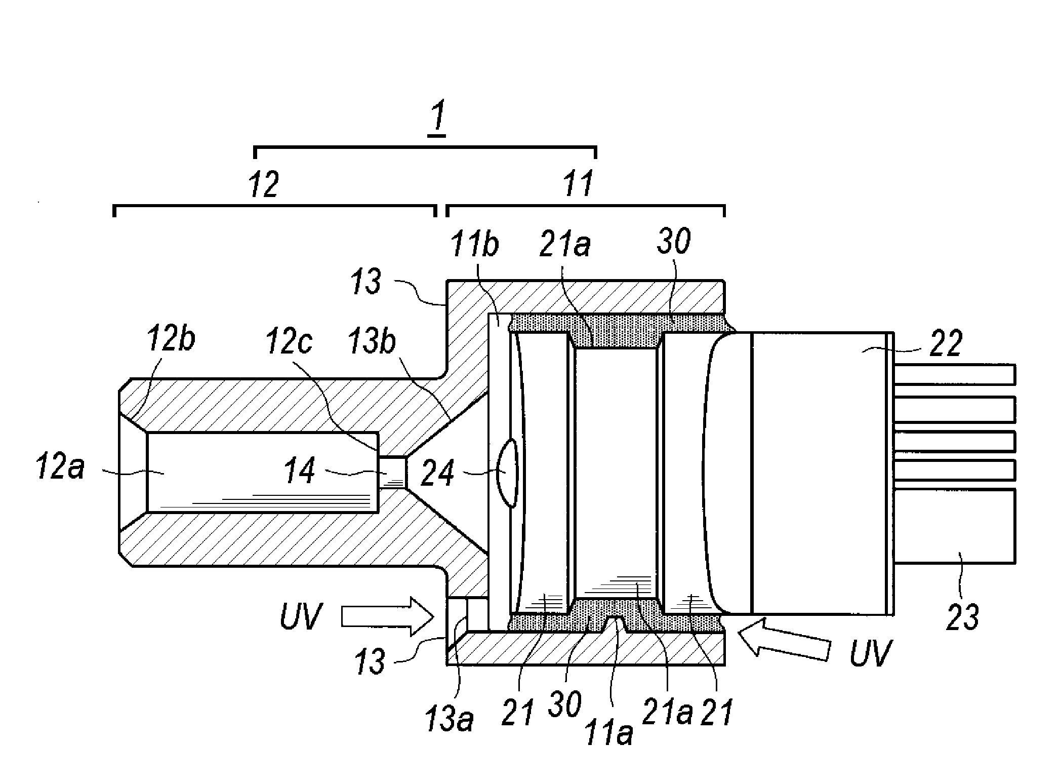
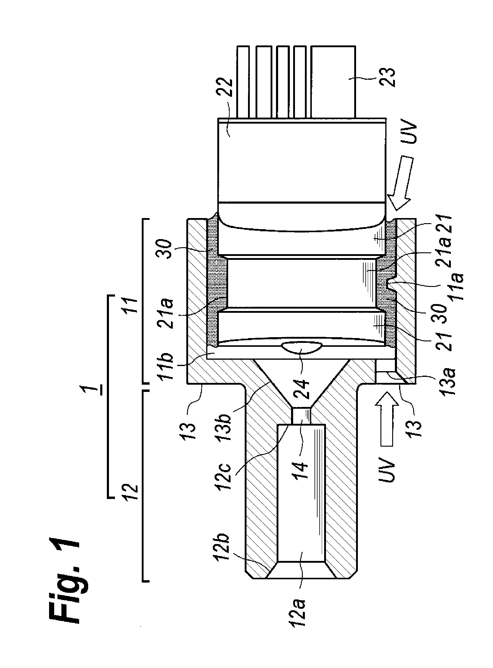
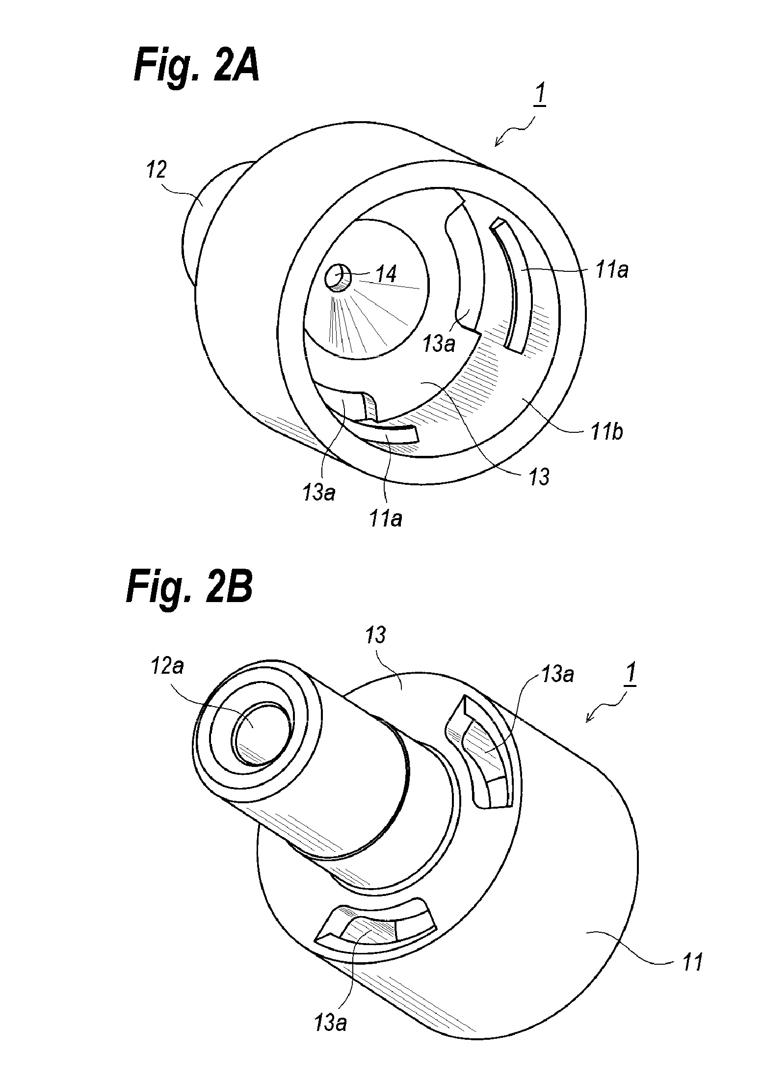
[0019]An optical subassembly (hereafter denoted as OSA) provides an optical device and an optical receptacle that sets the optical device therein. FIG. 1 is a cross section of the OSA according to the present embodiment; FIGS. 2A and 2B are perspective views of the optical receptacle, where FIG. 2A views from the bottom while FIG. 2B views from the top; and FIG. 3 is a perspective view of the optical device.

[0020]The optical receptacle 1 of the present embodiment has a cylindrical shape whose axis is along the optical axis of the OSA. The optical receptacle 1 includes a sheath portion 11, a sleeve portion 12, and a step 13 between the sheath portion 11 and the sleeve portion 12, as illustrated in FIGS. 2A and 2B. While, the optical device 2 includes a pillar portion 21 and a flat portion 22. The pillar portion 21 encloses, for instance, a semiconductor laser diode for a transmitter OSA or a semiconductor photodiode for a receiver OSA, which is not shown in FIG. 3. A plurality of lea...


PUM


Abstract

An optical subassembly is disclosed, in which an optical device is assembled with an optical receptacle using an anchor effect for the ultraviolet curable resin. The optical receptacle includes a sleeve portion that receives an external optical fiber and a sheath portion that receives the optical device. A bore formed in the sheath portion circumferentially provides a plurality of ribs; while the pillar portion of the optical device that encloses a semiconductor optical device provides a plurality of hollows in positions corresponding to the ribs. The rib shows the anchor effect for the resin filled within the hollow.

Description

BACKGROUND OF THE INVENTION[0001]1. Field of the Invention[0002]The present invention relates to an optical subassembly that provides an optical receptacle adhered to an optical device with a transparent resin package.[0003]2. Related Prior Art[0004]The YAG laser welding has been well known in the filed to assemble an optical receptacle with an optical device precisely and firmly. The YAG laser may heat members to be welded so as to melt them locally. Accordingly, the members to be welded are required to have a lesser thermal conductivity to cause the local melting even when they are metallic material.[0005]Recently, an optical subassembly primarily made of resin has been practical by responding to a continuous request to reduce the cost thereof, in particular, the optical subassembly for an application of the short reach has been strongly requested to lower the cost and the price. Such a subassembly often uses a resin package and an adhesive to assemble the subassembly. The optical...

Claims


Application Information

Patent Timeline
IPC IPC(8): G02B6/42
CPCG02B6/4239G02B6/4204
Inventor MIZUE, TOSHIOSAEKI, TOMOYA
Owner SUMITOMO ELECTRIC IND LTD
Why Eureka
Try Eureka