
Lower back supporter

a lower back supporter and support technology, applied in the field of new lower back supporters, can solve the problems of rash on the skin of the wearer, difficulty in handling, and difficulty in wearing tape, and achieve the effect of preventing slipping and being easy to wear

Active Publication Date: 2010-09-09
DAIYA IND +1
View PDF11 Cites 33 Cited by
  • Summary
  • Abstract
  • Description
  • Claims
  • Application Information

AI Technical Summary

Benefits of technology

[0008]The present invention is created taking into consideration of the problems described above with the conventionally lower back taping and lower back supporter, and it is an object of the present invention to provide a new lower back supporter which, while having the same function as conventional taping, does not have the above-described problems specific to taping and is as easy to wear as in a conventional lower back supporter, but is not uncomfortable to wear for a long time, and further is prevented from slipping while it is being worn.
[0012]In the lower back supporter of the present invention, when the anchor parts are put on the lower back, the inner side surfaces of the anchor parts closely contacts the skin of a wearer and does not slide, and the anchor parts play a role of anchor tape of conventional taping; and in addition, the first and second support belts that are connected to and fastened to that anchor parts have a role of a support tape of conventional taping. In addition, by wearing the supporter with slight tensile force applied by the anchor belts, the anchor belts play a role of securing a close contact of the anchor parts' inner side surface with the skin of the wearer and of eliminating the slippage. However, the anchor belts can be omitted. With the above-described structure, the lower back supporter of the present invention functions the same way as conventional taping and provides pressure, support, restriction and immobilization of the lower back, and it disperses the impact applied to the lower back and reduces and prevents recurrence of lower back pain; and it can be used instead of conventional taping.
[0013]The lower back supporter of the present invention is not directly put on the skin of a wearer using adhesive agent; accordingly, no concern of rash occurring on the skin of a wearer is required. Also, the same lower back supporter can be used any number of times, and it is less expensive than conventional taping. Furthermore, though it is necessary in conventional taping to rely on an expert when it is put on, the lower back supporter of the present invention can be easily worn by the patient just like conventional supporters; and after having it put on, if there is a sense of discomfort such as restriction, pressure or the like, it can be easily removed and then put back on, which is advantageous.
[0014]Furthermore, compared to the conventional lower back supporter, there is little pressure on the abdomen of the wearer, and thus it is possible to wear it for a long time, and slippage during wearing or the like is less likely to occur.

Problems solved by technology

However, the tape used in taping has problems.
It is difficult to handle when it is being applied because of its adhesiveness, and a rash would occur on the skin of a wearer due to the adhesive agent depending on the physical constitution of the patient.
In addition, tape removed from the body cannot be reused and has to be disposed of, and thus new tape is required with each application, and further it is necessary to have the tape applied by an expert.
However, since these supporters are of a type that may increase abdominal pressure to stabilize the lower back, there is a strong sensation of pressure on the abdomen, and the problem is that such supporters are uncomfortable and painful to wear for a long time, and they can slip easily while being worn (they can slip easily especially upward).

Method used


Image

  • Lower back supporter
  • Lower back supporter
  • Lower back supporter

Examples


Embodiment Construction

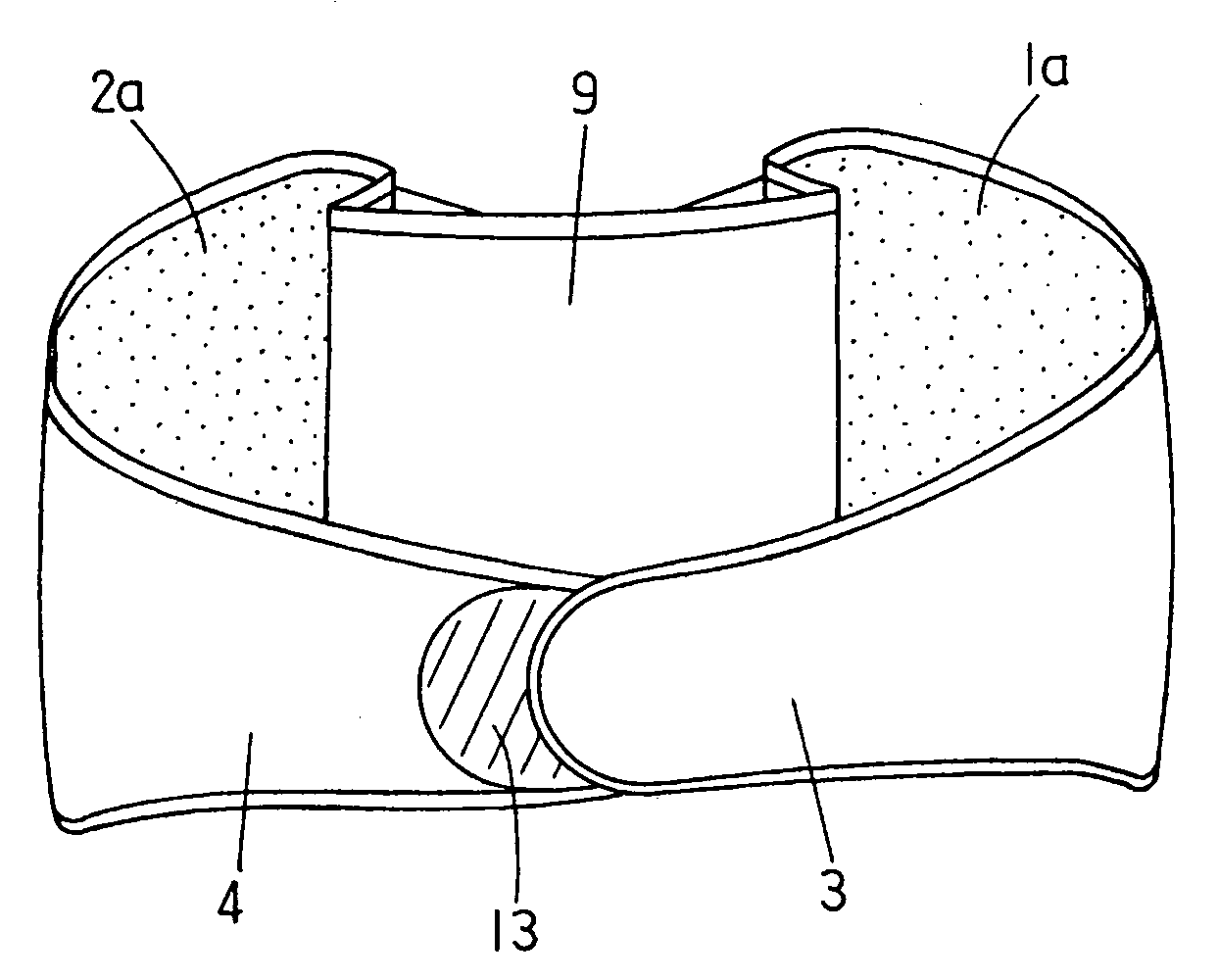
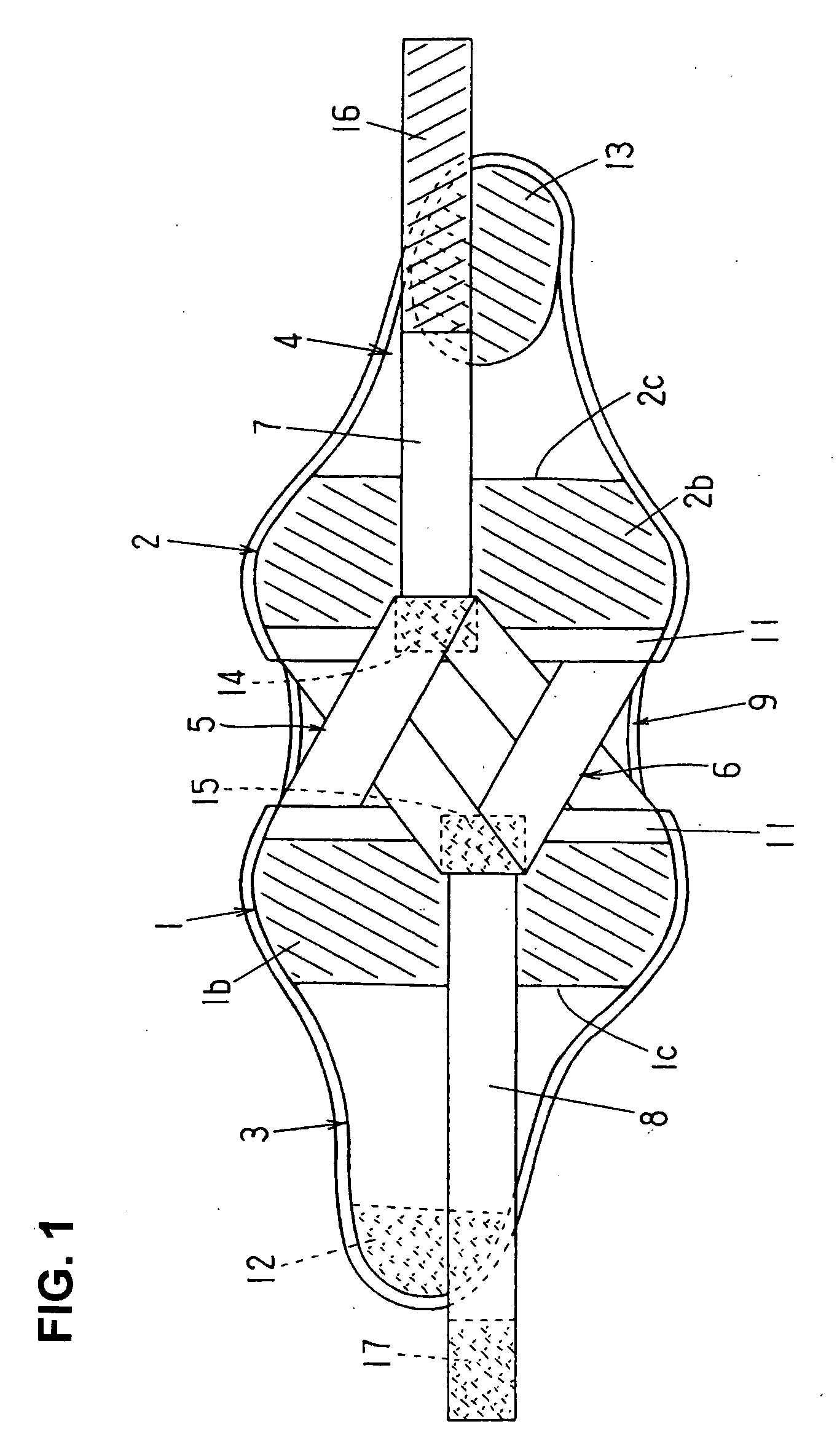
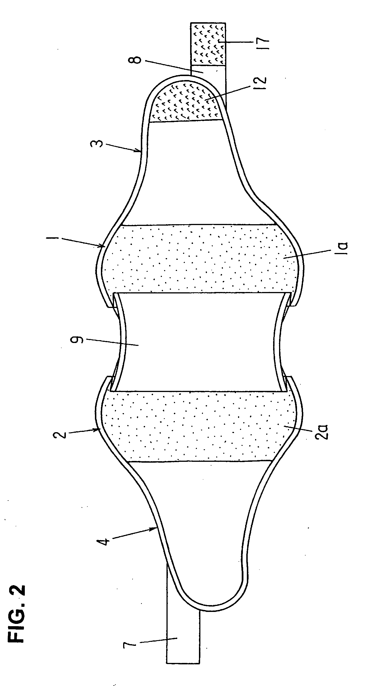
[0025]In the below, the lower back supporter of the present invention will be described in a more specific manner while referring to FIG. 1 through FIG. 10.

[0026]The lower back supporter shown in FIGS. 1 and 2 is comprised of a pair of anchor parts 1 and 2 arranged with a specified space in between and anchor belts 3 and 4 connected respectively to the anchor parts 1 and 2; and it is further comprised of a first support belt 5, which is connected to the anchor part 1 and brought to the anchor part 2 via the central back side of the lower back and fastened to the outer side surface of the anchor part 2, and a second support belt 6, which is connected to the anchor part 2 and brought to the anchor part 1 via the central back side of the lower back and fastened to the outer side surface of the anchor part 1. Operation belts 7 and 8 are respectively connected to the first and second support belts 5 and 6, and a connecting belt 9 is provided between the anchor parts 1 and 2 so as to conn...


PUM


Abstract

A lower back supporter including a pair of flat anchor parts that come into contact with the lower back of a wearer with a specified space in between, a pair of anchor belts that wrap around the abdomen with the end portions connected to each other, a first and second support belt that cross over each other on the back, and a connecting belt that connects the anchor parts. The inner side surface of the anchor part comprising a non-slip material that closely contacts the skin of the wearer, and the outer side surface comprising a material that fastens to surface fasteners. After the anchor belts are put on, operation belts connected to the first and second support belts are pulled, the surface fasteners are fastened to the outer side surfaces of the anchor parts, applying tensile force between the anchor parts in closely contact to the lower back.

Description

BACKGROUND OF THE INVENTION[0001]1. Field of the Invention[0002]The present invention relates to a new lower back supporter alternative to a known lower back taping which is used for reducing and preventing recurrence of lower back pain.[0003]2. Description of the Related Art[0004]In lower back taping, a tape that is made of cotton or chemical fiber or the like with an adhesive agent on its one surface is used, and the tape is applied diagonally and horizontally to the back of a patient from the sides to the center of the back so that it puts pressure on the lower back and supports, restricts and immobilizes the lower back, thus dispersing the impact applied to the lower back to reduce and prevent recurrence of lower back pain. Recently, taping has come to be used widely in particularly the sports field for the purpose of preventing injuries and for fast function recovery training or participation in games and the like (see “Practice and Theory of Taping from the Perspective of Spor...

Claims


Application Information

Patent Timeline
Patent Type & Authority Applications(United States)
IPC IPC(8): A61F5/00
CPCA61F5/028
Inventor IMAI, MASAYUKI
Owner DAIYA IND
Learn More