Fish Finder

a technology for fish finders and acoustic signals, applied in direction finders, instruments, measurement devices, etc., can solve the problems of limiting the ability of fish finders, reducing the usefulness of fish finders, and affecting so as to improve the signal to noise ratio

Active Publication Date: 2010-09-09
JOHNSON DAVID A
View PDF26 Cites 5 Cited by
  • Summary
  • Abstract
  • Description
  • Claims
  • Application Information

AI Technical Summary

Benefits of technology

[0008]In a first set of examples, a method for ultrasonic acoustic imaging of objects within a body of water is disclosed, the method includes the steps of: collecting a plurality of echo soundings over a period of time in an area of interest, the soundings produced by an ultrasonic transmitter and detected by one or more ultrasonic receivers, wherein each echo sounding includes a plurality of echo signals, the echo signals corresponding to an apparent vertical depth, thereby forming an unfocused image; collecting spatial location information of the transmitter and receiver, where the collected spatial location information is associated with each collected echo sounding; and forming a focused image. The step of forming a focused image further includes the steps of: selecting a focused signal spatial location where the selected focused signal spatial location is defined relative to the collected spatial location information associated with the echo soundings; selecting one or more echo soundings from the plurality of echo soundings; selecting an echo signal from each selected echo sounding, whereby the echo signal selection is determined by a calculation of which echo signal from the selected echo sounding corresponds to a focused signal occurring at the selected focused signal spatial location, where the calculation is based on the selected focused signal spatial location and on the collected spatial information associated with the selected echo sounding; combining the selected echo signals, whereby a focused echo signal with improved signal to noise ratio and correct spatial location is formed; and graphing the focused echo signal based on the selected focused signal spatial location, whereby a focused image is produced.

Problems solved by technology

The presence of fish in the water form obstacles to the acoustic signal.
This is an undesirable feature, as false positioning of the fish in the water decreases the usefulness of the fish finder.
This has the practical effect of severely limiting the ability of the fish finder to sharply define bottom structure of interest to fishermen.
These processing techniques are expensive, and designed for proper imaging of geologic formations under the surface of the water bottom.
The frequencies, spacings and design of the sources and receivers are typically not suited for detection of fish in the water.

Method used


Image

  • Fish Finder
  • Fish Finder
  • Fish Finder

Examples


Embodiment Construction

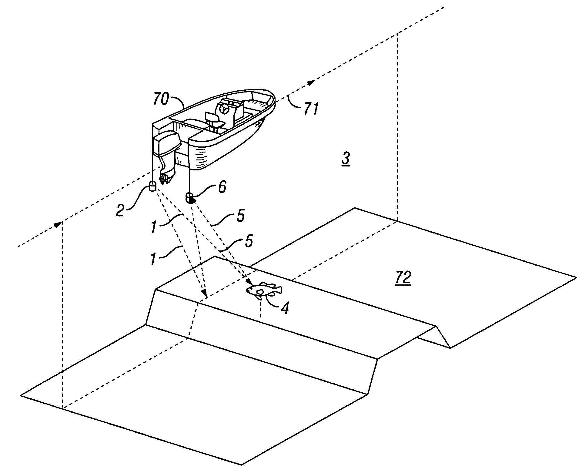
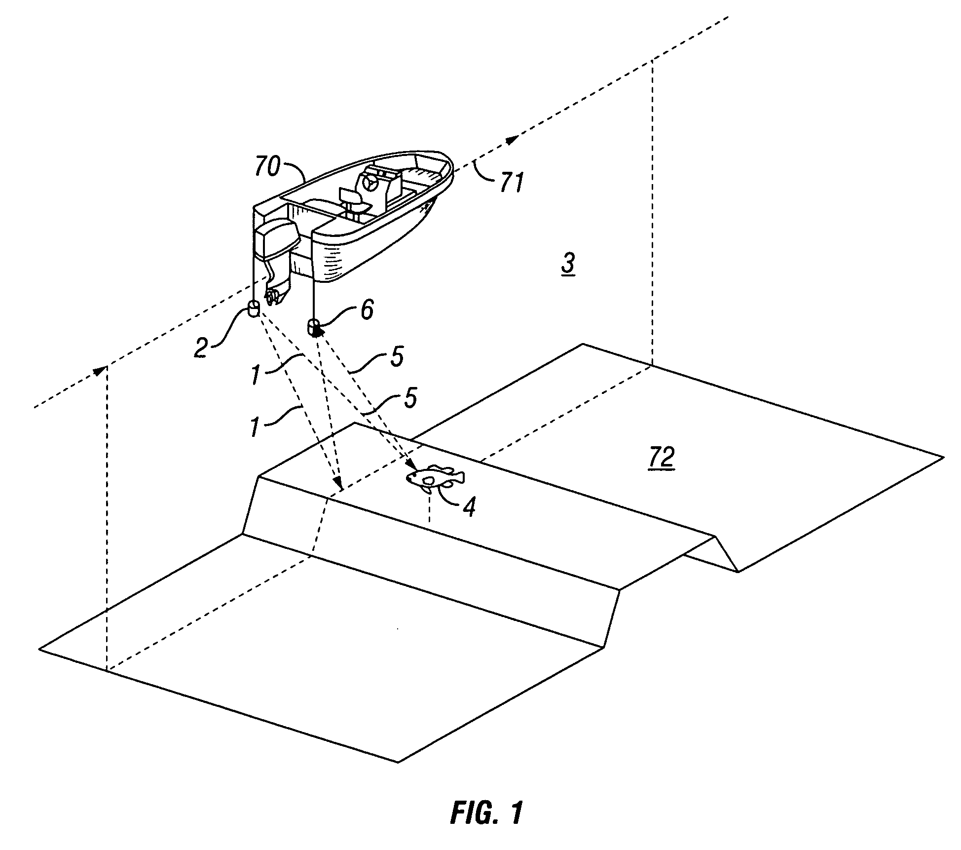
[0038]FIG. 1 illustrates a diagrammatic view for ultrasonic acoustic imaging of objects within a body of water. In one example, acoustic signals 1 are produced by an ultrasonic transmitter 2 placed in a body of water 3. Ultrasonic transmitter 2 and ultrasonic receiver 6 are deployed in body of water 3 by a boat 70. Boat 70 travels along a course 71. Acoustic signals 1 reflect off of objects 4 and their reflected echoes 5 are detected by an ultrasonic receiver 6. Fish in water are examples of objects 4 that produce reflected echoes. In one example, transmitter 2 and receiver 6 are located in approximately the same spatial location. In another example, transmitter 2 and receiver 6 are located at differing spatial locations. In another example, there are a multitude of ultrasonic transmitters 2 and ultrasonic receivers 6.

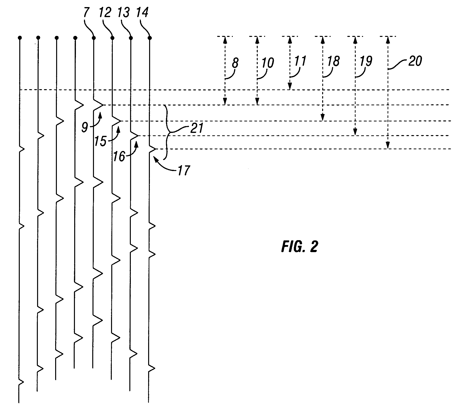
[0039]FIG. 2 illustrates a diagrammatic view of echo soundings and collected echo signals. As shown in FIG. 2, the collection of reflected echoes 5 from a transmitted ...


PUM


Abstract

A method, system, and apparatus are provided for focused ultrasonic acoustic imaging of objects within a body of water. A plurality of echo soundings are collected, the soundings produced by an ultrasonic transmitter and detected by an ultrasonic receiver. Spatial location information of the transmitter and receiver is collected and associated with each collected echo sounding. A focused signal spatial location is selected. One or more of the collected echo soundings are selected. An echo signal from each selected echo sounding is selected. The echo signal selection is determined by a calculation of which echo signal from the selected echo sounding corresponds to a focused signal occurring at the selected focused signal spatial location. The calculation is based on the selected focused signal spatial location and on the collected spatial information associated with the selected echo sounding. The selected echo signals are combined, whereby a focused echo signal is formed. The focused echo signals are graphed based on their respective selected focused signal spatial locations, whereby a focused image is produced.

Description

FIELD OF THE INVENTION[0001]The invention relates to the field of fish finders. More specifically, the present invention is a method, apparatus, and system for forming focused images of fish and other submerged objects in water.BACKGROUND[0002]Fish finders typically use an acoustic signal that is pulsed into the water. The presence of fish in the water form obstacles to the acoustic signal. Some of the acoustic signal will reflect off the fish and return to an acoustic receiver designed to listen for the returning acoustic signal(s). It is possible to approximate the depth of the fish by recording the time taken for the return of the acoustic signal. The results can be displayed graphically such that longer return times are plotted downward from an imaginary sea level or water surface.[0003]After a period of time, after listening for any returning acoustic signals, another pulse of the acoustic signal is repeated. The period of time for listening is repeated. Assuming that the boat ...

Claims


Application Information

Patent Timeline
Patent Type & Authority Applications(United States)
IPC IPC(8): G01S15/96G01S15/02G01S15/10
CPCG01S7/52003G01S15/96G01S15/89G01S15/42
Inventor JOHNSON, DAVID A.
Owner JOHNSON DAVID A
Why Eureka
Try Eureka