
Durable Ice Auger Mounting System that Maximizes Mobility and Support for Auger Device

a technology of mounting system and auger device, which is applied in the field of augers, can solve the problems of affecting the use of auger devices, affecting the mobility of auger devices, and affecting the use of existing auger mounting systems,

Inactive Publication Date: 2010-09-09
JOHNSON CLINT +2
View PDF28 Cites 19 Cited by
  • Summary
  • Abstract
  • Description
  • Claims
  • Application Information

AI Technical Summary

Problems solved by technology

However, because of their shape and weight, hand-held, power driven augers are bulky to transport and can be difficult to use.
Additionally, the vibration of the auger can cause fatigue when supporting the auger during drilling, and transporting.
There are many difficulties known in the prior art with respect to existing auger mounting systems for mounting an auger on a vehicle.
Both metal and plastic parts are known to malfunction in cold temperatures and the vehicle may shift from its original postion on icy surfaces or from the motion of the auger.
Scott '470 provides support for an auger and faciltates transport of the auger; however, the range of motion of the device is limited to a vertical axis.
The limitation to a vertical axis means that the vehicle must be moved each time a new hole is drilled.
Furthermore, if the vehicle shifts in postion on a slippery surface, the auger cannot be easily adjusted or repositioned to promptly compensate for the shift of the vehicle.
However, the design of these auger mounting systems interferes with the functionality of the vehicle.
As a result, the ATV cannot haul cargo or pull a trailer without first removing the auger and the auger holder from the vehicle.

Method used


Image

  • Durable Ice Auger Mounting System that Maximizes Mobility and Support for Auger Device
  • Durable Ice Auger Mounting System that Maximizes Mobility and Support for Auger Device
  • Durable Ice Auger Mounting System that Maximizes Mobility and Support for Auger Device

Examples


Embodiment Construction

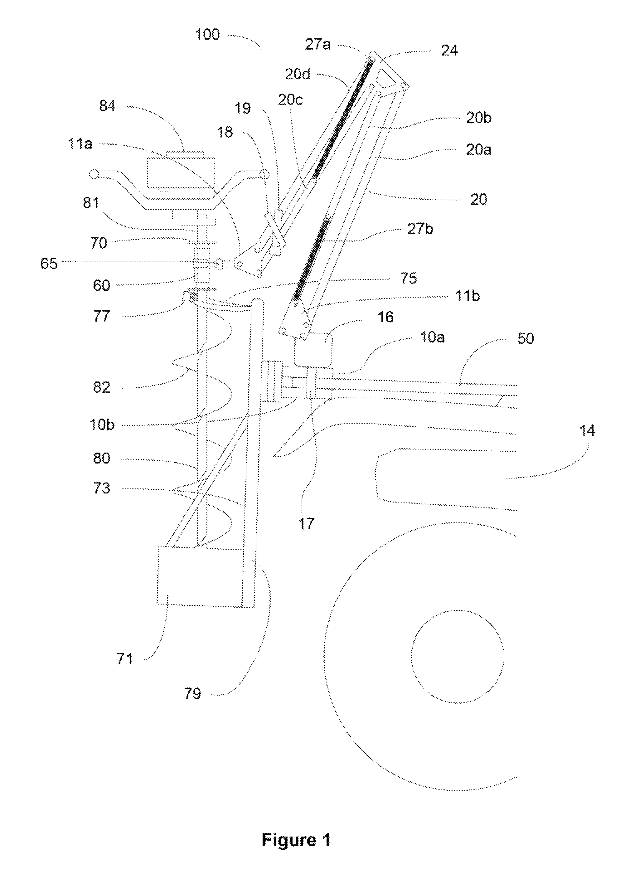
[0042]For the purpose of promoting an understanding of the present invention, references are made in the text to exemplary embodiments of an ice auger mounting system, only some of which are described herein. It should be understood that no limitations on the scope of the invention are intended by describing these exemplary embodiments. One of ordinary skill in the art will readily appreciate that alternate but functionally equivalent materials, components and designs may be used. The inclusion of additional elements may be deemed readily apparent and obvious to one of ordinary skill in the art. Specific elements disclosed herein are not to be interpreted as limiting, but rather as a basis for the claims and as a representative basis for teaching one of ordinary skill in the art to employ the present invention.

[0043]It should be understood that the drawings are not necessarily to scale; instead, emphasis has been placed upon illustrating the principles of the invention. In addition,...


PUM


Abstract

The present invention is an auger transport and mounting system which facilitates the drilling and positioning of ice fishing or other holes in an outdoor surface.

Description

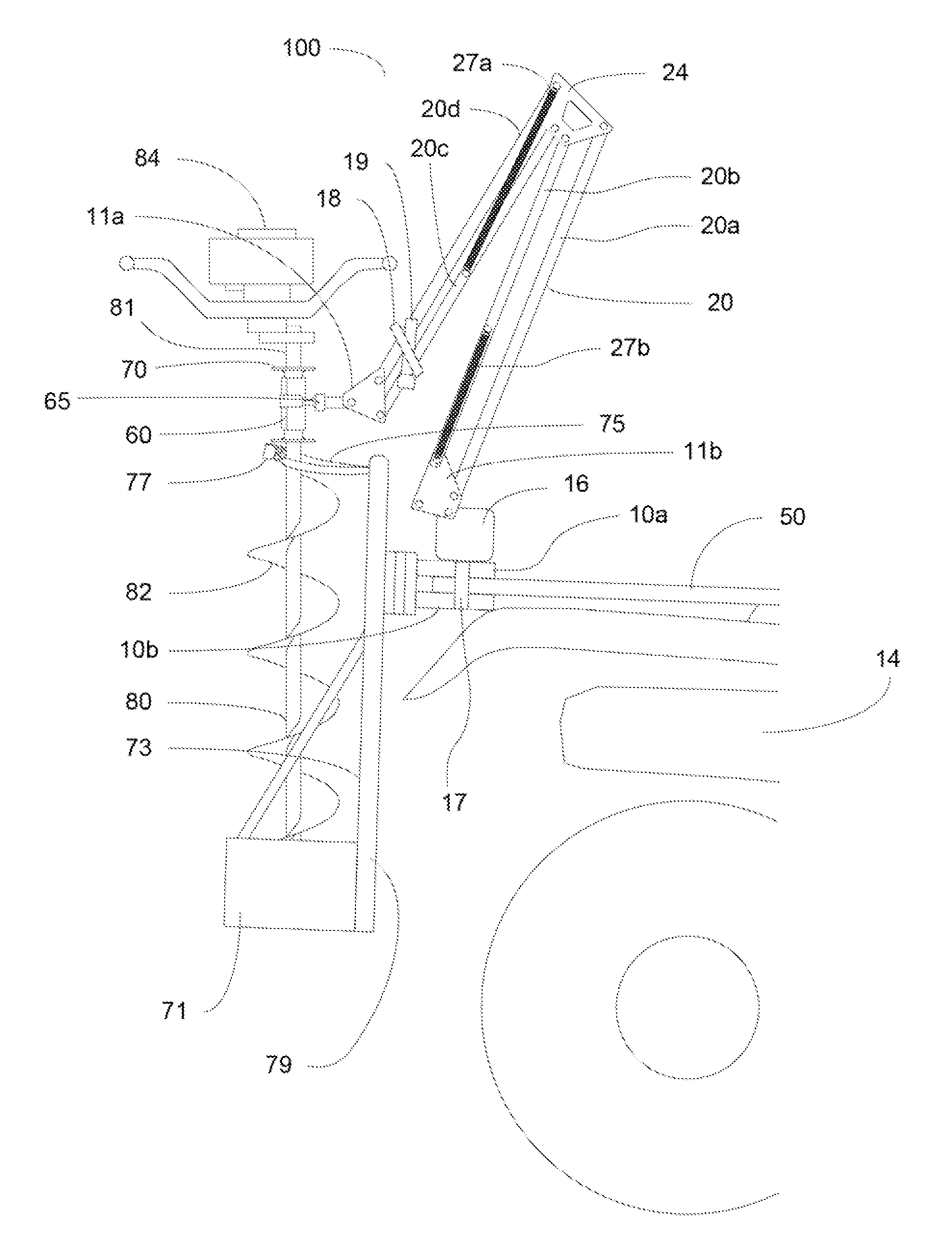
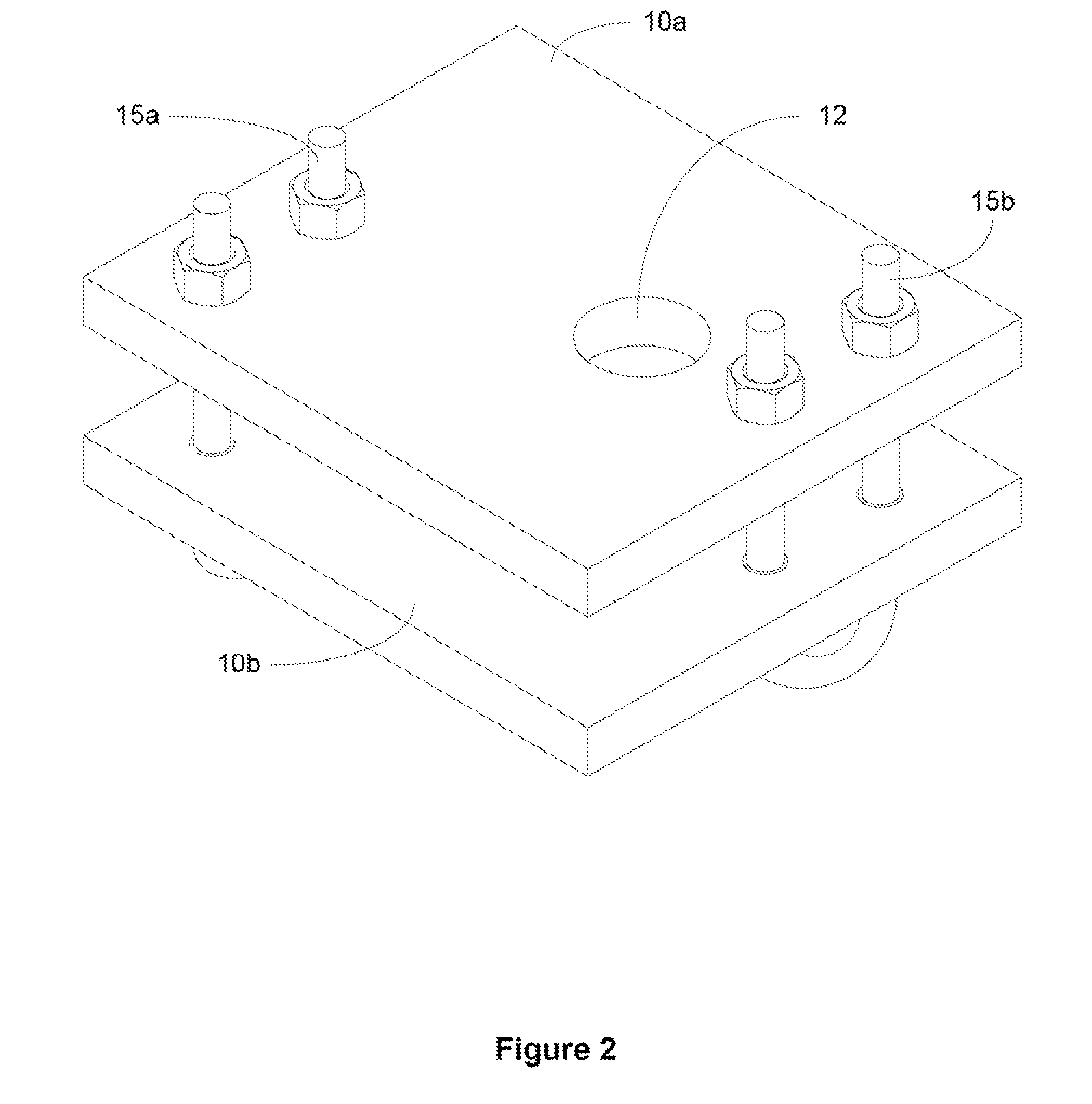
CROSS-REFERENCE TO RELATED APPLICATIONS [0001]This application claims priority to U.S. Provisional Application No. 61 / 157,479 filed on Mar. 4, 2009.FIELD OF INVENTION [0002]The present invention relates generally to augers and more specifically to auger mounting assemblies for use with any motor vehicle, and which further includes features to support and stabilize an auger when it is in use.BRIEF DESCRIPTION OF THE DRAWINGS[0003]FIG. 1 illustrates a side view of an exemplary embodiment of an auger mounting system mounted on an all-terrain vehicle (ATV).[0004]FIG. 2 illustrates a perspective view of an exemplary embodiment of mounting plates for an auger mounting system.[0005]FIG. 3 illustrates a perspective view of an exemplary embodiment of an auger collar for an auger mounting system.[0006]FIG. 4 illustrates a side view of an exemplary embodiment of a hinged arm component for an auger mounting system.[0007]FIG. 5a illustrates a side view of an exemplary embodiment of a quick relea...

Claims


Application Information

Patent Timeline
Patent Type & Authority Applications(United States)
IPC IPC(8): F16M13/00
CPCE21B7/028E21B7/008
Inventor JOHNSON, CLINTGAPP, STEVEFELTON, JOHN REED
Owner JOHNSON CLINT
Learn More