
Canarded deltoid main wing aircraft

a canard-type, main-wing aircraft technology, applied in the direction of canard-type aircraft, wing shapes, transportation and packaging, etc., can solve the problems of difficult to build a realistic aircraft capable of takeoff and landing on its own, jeopardizing the flight safety of aircraft, etc., to achieve a large, simple and highly aerodynamically efficient design, the effect of increasing the payload and airlifting capacity

Inactive Publication Date: 2010-09-09
DIZDAREVIC FARUK +1
View PDF6 Cites 5 Cited by
  • Summary
  • Abstract
  • Description
  • Claims
  • Application Information

AI Technical Summary

Benefits of technology

"The canarded deltoid main wing aircraft design has several technical advantages over traditional supersonic aircraft. It has a simple and highly aerodynamic efficient body that allows for a higher payload and airlifting capacity compared to other designs. The canards are positioned in front of the gravity center at a long distance to provide efficient pitch control and extra lift production during takeoff and landing. The design also minimizes interference drag and allows for the safe transfer of all aerodynamic and inertia forces. Overall, the canarded deltoid main wing aircraft design provides a high ride quality and flight safety with a relatively small wetted area and low interference drag."

Problems solved by technology

The Hypersoar aircraft represents a theoretical optimization of aircraft exclusively for hypersonic speeds, whereas it would be very difficult to be built as a realistic aircraft that is capable for takeoff and landing on its own.
However, a significant disadvantage of this concept is related to inability to use trailing edge devices for extra lift production, thus requiring a high landing speed at high attack angles, hence jeopardizing the flight safety of aircraft.

Method used


Image

  • Canarded deltoid main wing aircraft
  • Canarded deltoid main wing aircraft
  • Canarded deltoid main wing aircraft

Examples


Embodiment Construction

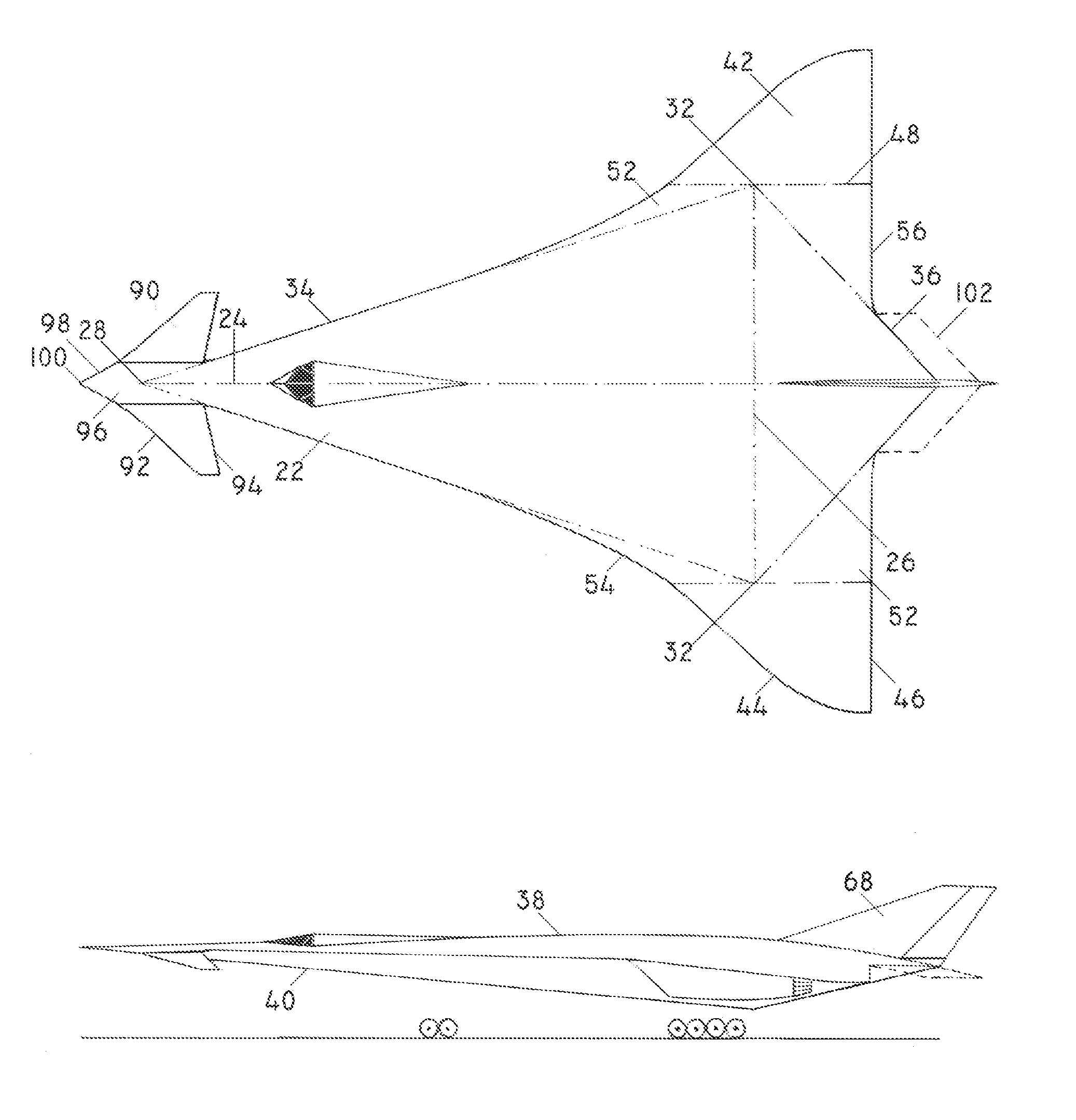
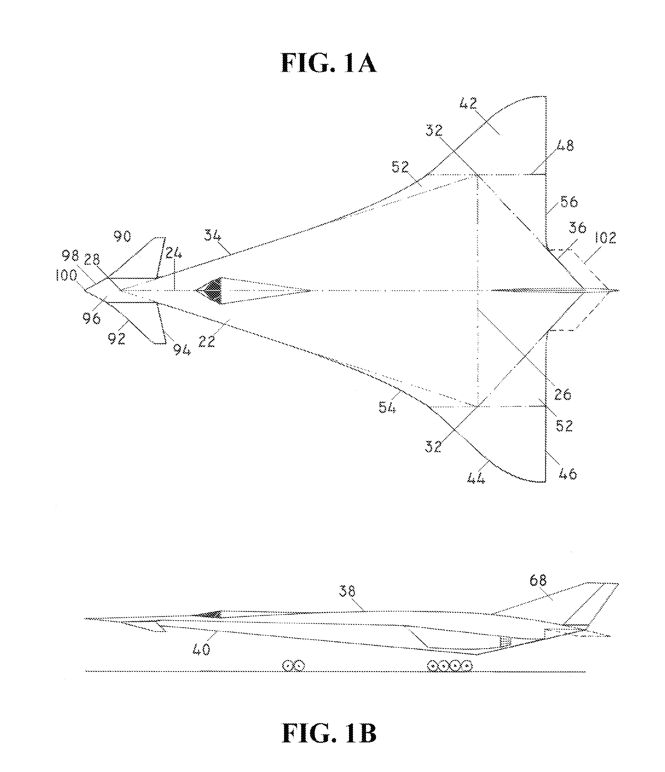
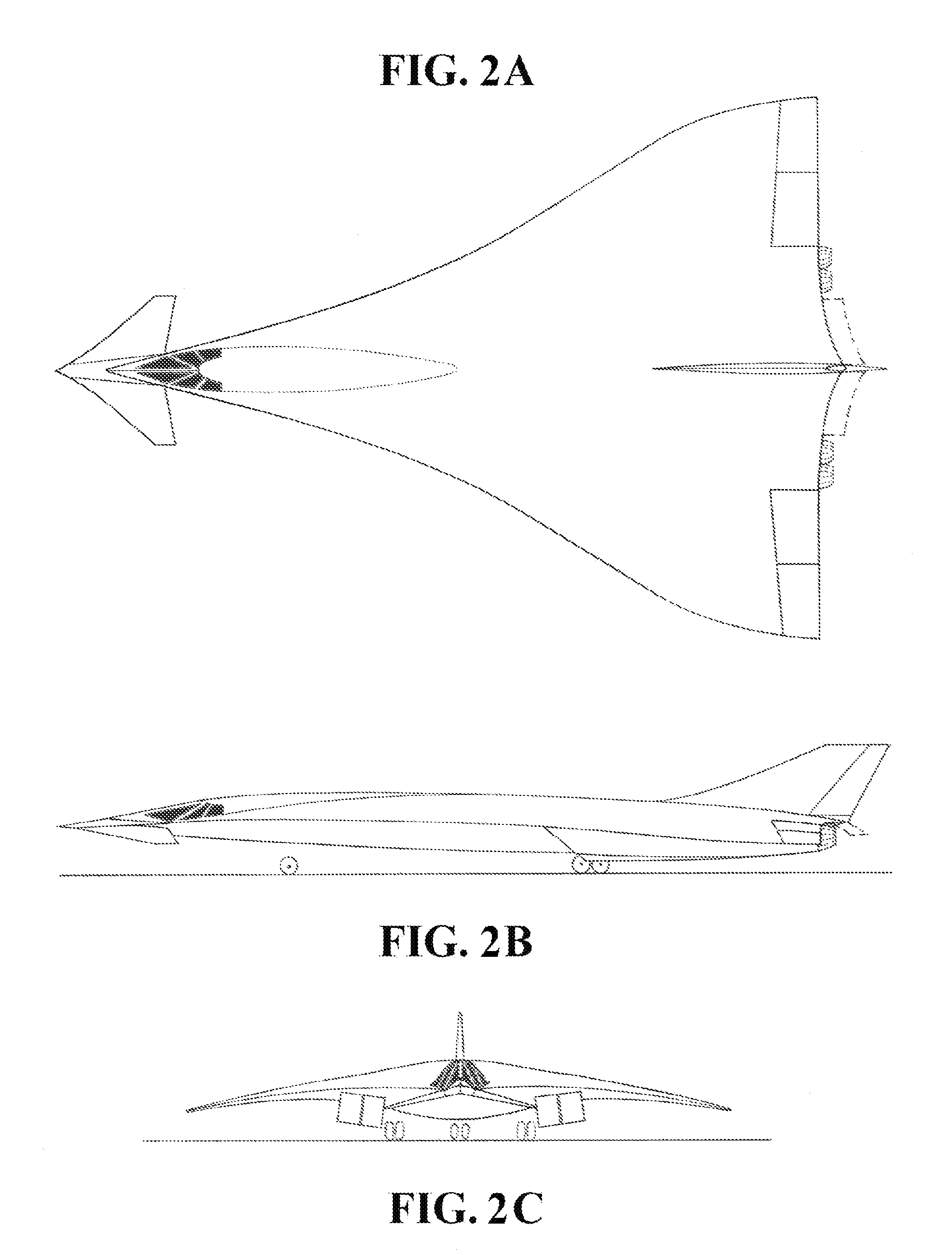
[0045]FIGS. 1, 2, and 3 show aircraft that are based on a Canard Deltoid Main Wing (CDMW) aerodynamic configuration with all-pivotal canard sections (90). This aerodynamic configuration includes main wing (22), outer wings (42), and outer wing transition sections (52) that constitute the integral airlifting surface of aircraft, as well as canard sections (90) and canard connecting means (96). The longitudinal diagonal (24) of the main wing has a highly pronounced fore position relatively to transversal diagonal (26) in order to provide for a high efficiency of canard sections (90) in pitch control of aircraft (FIGS. 1, 2, and 3). A distinctly fore position of longitudinal diagonal (24) is providing for a high sweepback angle of main wing leading edge (34) and a distinctly aft position of lateral tips (36) where outer wings (42) are joined main wing (22), thereby CDMW aerodynamic configuration being applicable for high transonic and supersonic aircraft. Main wing (22) is distinctly l...


PUM


Abstract

Canarded deltoid main wing aircraft idea allows for design of large supersonic civil and military aircraft with cruising speeds of up to Mach 3 at the altitude of over 25,000 meters. The fuel consumption per unit of payload of such aircraft would be at least twice lower with a longer range of over 50% when compared to existing supersonic aircraft of the same size. Simultaneously, the flight safety and ride quality during takeoff and landing at low speeds would be similar to the existing subsonic passenger aircraft. A low fuel consumption, long range, high ride quality, and high flight safety of these aircraft are widely opening a door for design of supersonic long range continental and intercontinental passenger aircraft that would be highly competitive with existing long range high subsonic passenger aircraft.

Description

BACKGROUND OF INVENTION[0001]Supersonic speeds generally require sharp front edges of flying objects with high sweepback angles to generate smallest possible front shock waves, as well as small wetted and airlifting area. These requirements for low wetted and airlifting area, as well as a low pitch control efficiency of flying wing objects that have large airlifting area are the main reason as to why there have been very few prior embodiments based on flying wing idea for supersonic aircraft.[0002]One of the few prior art embodiments based on flying wing ideas is “Hypersoar” project. It represents a typical example of the flying wing idea for high supersonic and hypersonic aircraft. It is based on “Wave Rider” theoretical principle for the airlift generation of objects flying at hypersonic speeds, which further involved the integration of scramjet engines on the trailing edge of the lower surface of the aircraft. The Hypersoar aircraft represents a theoretical optimization of aircra...

Claims


Application Information

Patent Timeline
Patent Type & Authority Applications(United States)
IPC IPC(8): B64C39/12
CPCB64C1/0009B64C3/10Y02T50/12B64C39/12B64C2039/105B64C30/00Y02T50/10B64U30/10B64U50/13B64U20/77B64U2101/60
Inventor DIZDAREVIC, FARUKDIZDAREVIC, MITHAD
Owner DIZDAREVIC FARUK
Learn More