Eureka AIR delivers breakthrough ideas for toughest innovation challenges, trusted by R&D personnel around the world.

Braided Fiber Optic Cross-Connect Switches

Active Publication Date: 2010-09-02
TELESCENT
View PDF5 Cites 23 Cited by
  • Summary
  • Abstract
  • Description
  • Claims
  • Application Information

AI Technical Summary

Benefits of technology

[0013]This fiber optic cross-connect system thus utilizes a multiplicity of fiber optic strands disposed in a spatially coherent configuration with interconnections having different path lengths between a fixed configuration of strand guides parallel to one axis at one plane and interconnected to variable positions along a second two-dimensional plane. A modular, expandable system of rotatable reels enables the interconnections at the plane of the two-dimensional matrix to be varied while maintaining tension and more than a minimum radius of curvature on the optical fiber strands.
[0015]In accordance with the invention, a method of and apparatus for dynamically reconfiguring a fiber optic interconnection within an interconnect volume including a large number of spatially coherent fiber optic interconnections defining vectors and spanning a regular two-dimensional array of inputs and ordered outputs are disclosed. Robotic manipulation of an affected optical fiber surrounded by a multiplicity of unaffected optical fibers is performed by traversing the unaffected optical fibers in alternating positive and negative interweaves with both column traversals and transverse row shifting alternating in direction as commanded, forming a multiplicity of separate, strictly positive or negative non-repeating subbraids. The robotic manipulation trajectory passes individually through one or more of the subbraids defining a column by programmed splitting of the subbraids into two partial sub-subbraids. The splitting is adequate for non-interfering passage of the affected fiber through the split in the subbraid. The two partial subbraids are then merged after the passage by affected fiber is complete. This interweaving concept materially reduces the time needed for reconfiguration.
[0016]Systems and methods in accordance with the invention include numerous features that facilitate assembly and operation of the reconfiguration system. Length variations in the fiber optic strands are accommodated in low elevation reel bodies mounted within shallow height modules which can be inserted in a grouped system configuration. The reels themselves provide circumferential bias on the interior fiber optic elements, because an elongated spring coextensive with the fiber optic element is wound helically within the reel, between input and output, so that the system can withdraw a length of fiber optic strand from the reel while maintaining tension to retract the fiber optic element as needed. In addition, the reel incorporates a rotational encoder in the form of regular incremental variations concentric with its central axis, which variations are optically detected to provide an accurate reading as to the amount of fiber optic strand that has been withdrawn from the reel. With these low elevation housings arranged compactly at different stacking heights (e.g. four high), a number of layers of reels can be incorporated within each module, providing a multiplicity of fiber optic strands that extend outwardly into a three-dimensional module volume, enabling reconfiguration by a gripper and positioning system. With the spring element and optical fiber coextensively disposed within a flexible or compliant housing, a spring of appropriate compliance is all that is required for maintaining the optical fiber strand under a controlled tension for withdrawal, and for subsequent return into the reel. In this system, the reconfigurable input terminals of the array extend to the wall of the system housing.

Problems solved by technology

Consequently, the tasks of allocating, reconfiguring and testing a fiber circuit within the network is challenging.
There is significant potential for errors or damage resulting from manual changes to the physical network configuration.
Prior art automated cross-connect approaches have not been modular and as such, they do not offer an upgrade path from 200 ports to 1000 ports, for example.
This approach increases cost, complexity and reduces optical performance because of the need to transmit through a series arrangement of three switches rather than one.
The optical performance of prior art robotic cross-connects is inferior to manual patch-panels because they introduce an additional fiber optic connection in series with each fiber circuit.
This increases the loss by at least a factor of 2 above manual systems.
However, the scalability of these prior art robotic versions has been limited.
Current technologies have been unable to achieve these varied requirements.

Method used


Image

  • Braided Fiber Optic Cross-Connect Switches
  • Braided Fiber Optic Cross-Connect Switches
  • Braided Fiber Optic Cross-Connect Switches

Examples


Embodiment Construction

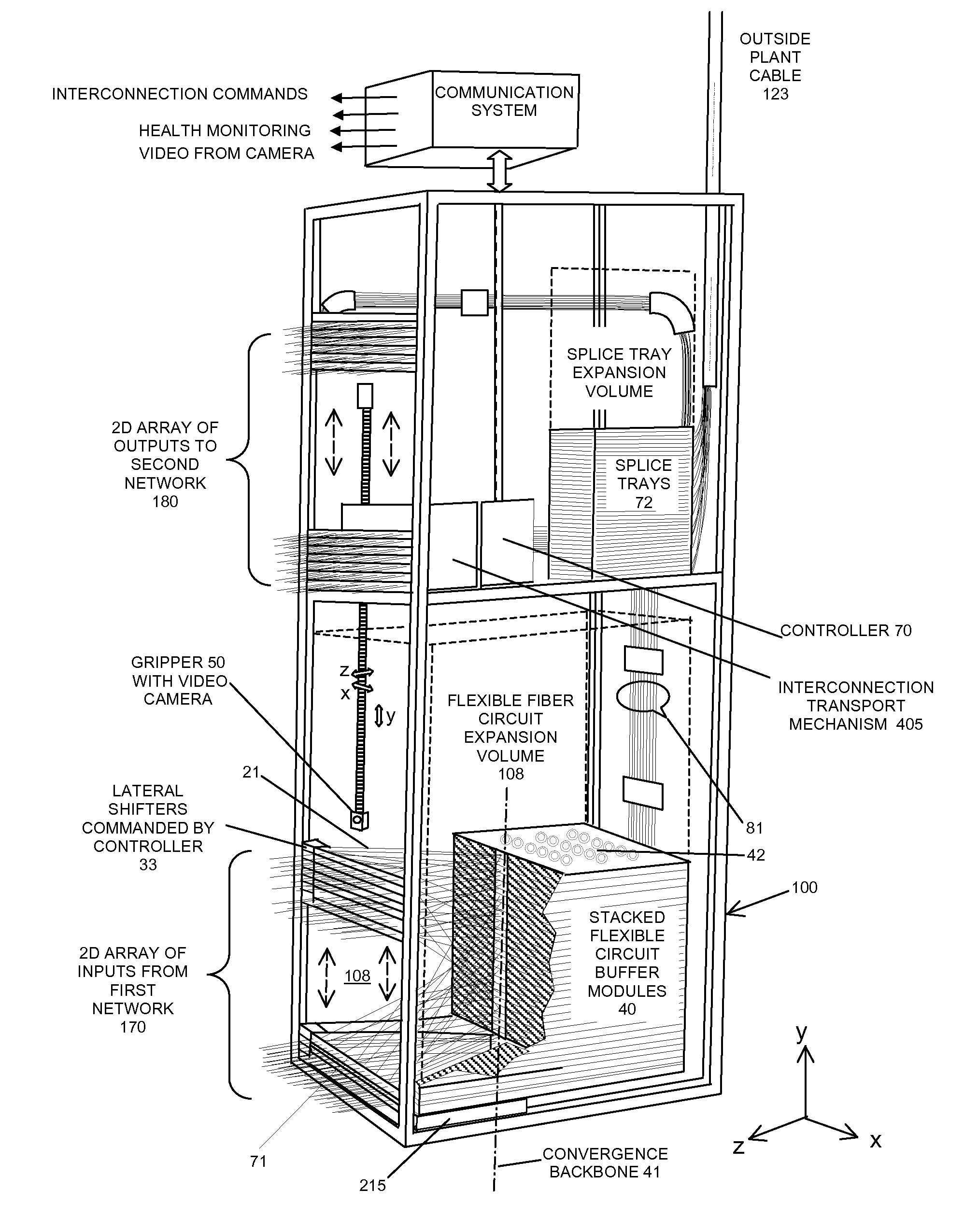
[0043]The all-fiber cross-connect switching system disclosed in this invention is illustrated in the partial cutaway, perspective view of FIG. 1. This system is characterized by 100's to 1000's of flexible fiber interconnection lines or strands 21 suspended between two planes and intermixing within a circuit expansion volume 108 in the system interior. The placement, ordering and subsequent physical reconfiguration of strands is based on relationships derived from the Theory of Knots and Braids. Topological algorithms uniquely describe the dynamic nature of strand boundary conditions during the reconfiguration process.

[0044]Reconfigurable fiber connections are made internal to the expansion volume 108, between a two-dimensional array of reconfigurable input terminals 170 and an intermediate, substantially one-dimensional array or convergence backbone 41 bounding the interconnect volume. The suspended fiber lines 21 therebetween follow substantially straight-line paths and define a t...


PUM


Abstract

This invention discloses a highly scalable and modular automated optical cross connect switch comprised of large numbers of densely packed fiber strands suspended within a common volume. In particular, apparatus and methods enabling programmable interconnection of large numbers of optical fibers (100's-1000's) having structured and coherent braid representations are provided.

Description

REFERENCE TO RELATED APPLICATIONS[0001]This application is a continuation-in-part of U.S. patent application Ser. No. 12 / 196,262, filed on Aug. 21, 2008 and entitled “Scalable and Modular Automated Fiber Optic Cross-Connect Switch”, U.S. patent application Ser. No. 12 / 196,266, filed on Aug. 21, 2008 and entitled “Methods to Reconfigure All-Fiber Optical Cross-Connects”, and further relies for priority on provisional application No. 61 / 178,961, filed on May 16, 2009 and entitled “Braided Fiber Optic Cross-Connect Switches”.FIELD OF THE INVENTION[0002]This invention relates to reconfigurable fiber optic cross-connect systems, and more particularly, to apparatus, systems and methods to reconfigure flexible fiber circuits at a rapid rate within a volume shared by large numbers of adjacent and intermixed fiber circuits.BACKGROUND OF THE INVENTION[0003]Fiber optic cross-connects and patch-panels are used to terminate large numbers of optical fibers at an array of connectors, providing a c...

Claims


Application Information

Patent Timeline
IPC IPC(8): G02B6/26G02B6/00B65H75/48
CPCG02B6/3502G02B6/3564G02B6/4458G02B6/4452G02B6/4457G02B6/3897
Inventor KEWITSCH, ANTHONYGREENBERG, SETHHUDSON, PAUL
Owner TELESCENT
Why Eureka
Eureka Blog
Learn More