
Video coding method and video decoding method

Inactive Publication Date: 2010-09-02
PANASONIC CORP
View PDF7 Cites 77 Cited by
  • Summary
  • Abstract
  • Description
  • Claims
  • Application Information

AI Technical Summary

Benefits of technology

[0073]The video coding method, the video decoding method, the device using the video coding method, and the device using the video decoding method according to the present invention can optimize prediction efficiency and coding efficiency.

Problems solved by technology

Especially for motion vectors with sub-pel resolution, effects like aliasing, quantization errors, errors from inaccurate motion estimation, camera noise, and the like limit the prediction efficiency of motion compensation.
Separable adaptive interpolation filters have a lower number of independent filter coefficients than non-separable filters, resulting in reduced computational complexity for applying and coding the filters.
However, this also implies a reduced number of degrees of freedom and thus fewer possibilities to improve the prediction efficiency compared to non-separable filters.
This may lead to a lower coding efficiency than with a non-separable filter.
However, non-separable adaptive interpolation filters have a higher number of independent filter coefficients than separable filters, resulting in increased computational complexity.
If an implementation has to safe computational complexity, it will apply a separable filter resulting in a possibly non-optimal prediction.

Method used


Image

  • Video coding method and video decoding method
  • Video coding method and video decoding method
  • Video coding method and video decoding method

Examples


Embodiment Construction

[0123]The following describes a video encoder and a video decoder according to a preferred embodiment of the present invention with reference to the drawings.

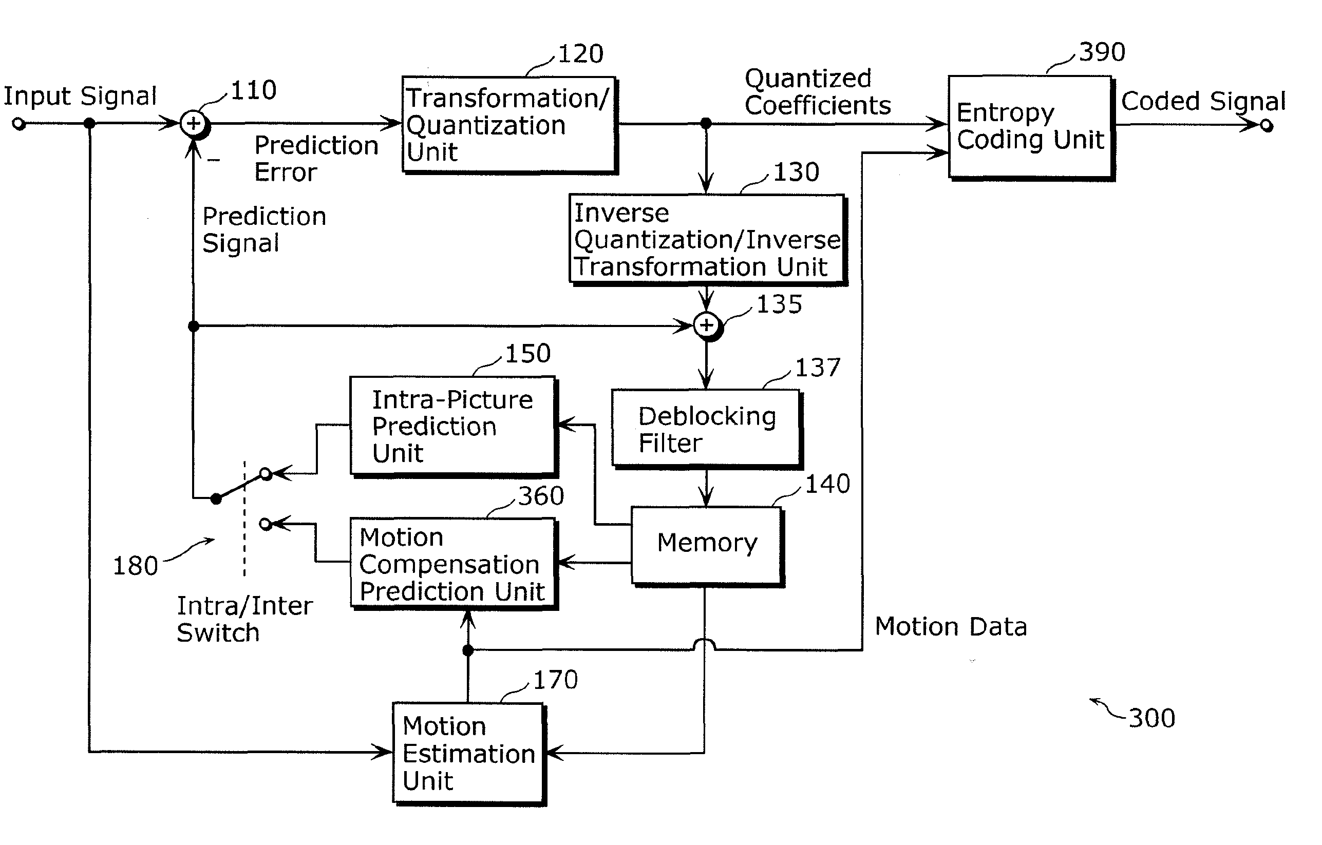
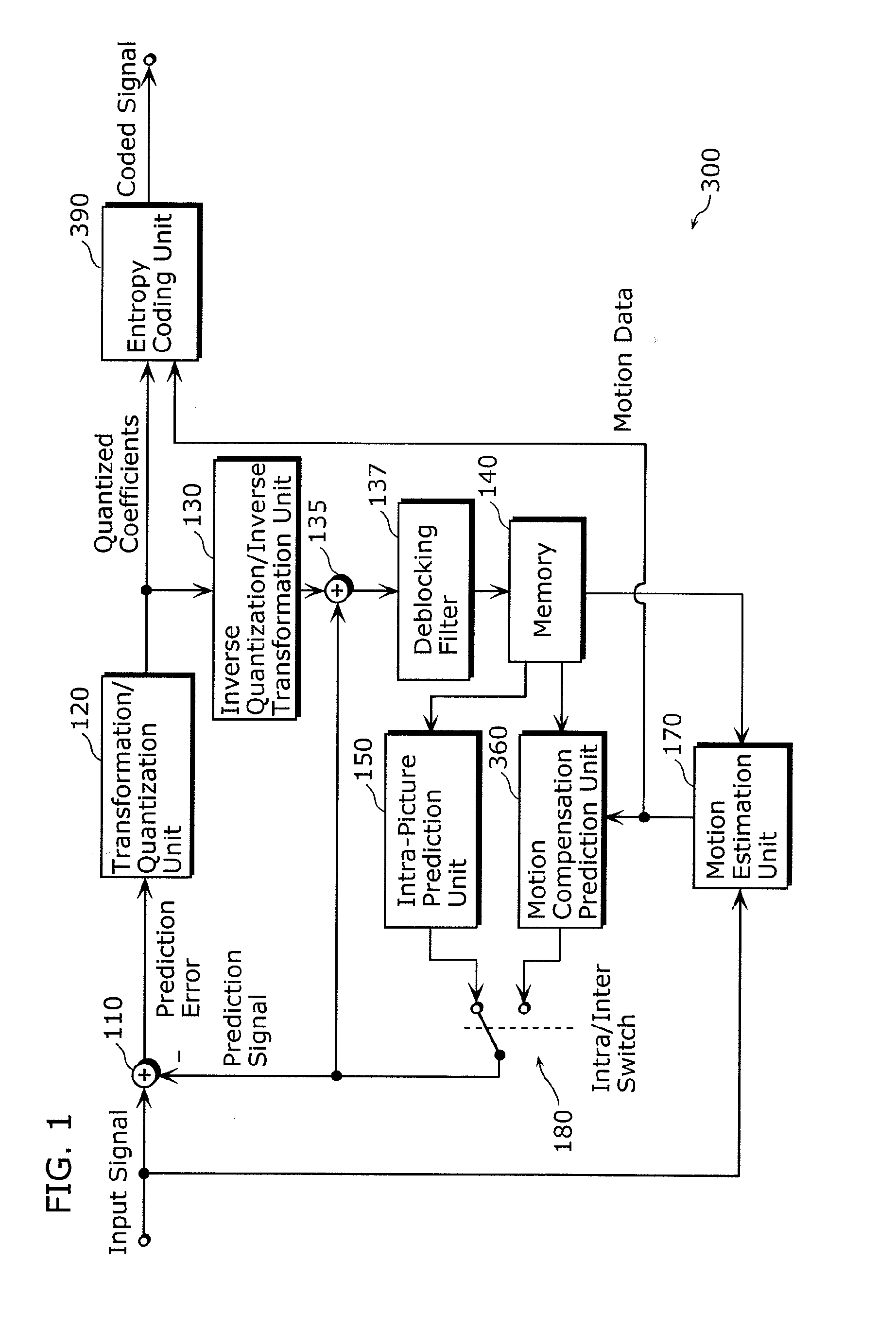
[0124]FIG. 3 is a block diagram illustrating a structure of a video encoder 100 applying motion compensation with adaptive filtering according to the embodiment of the present invention. The video encoder 100 in FIG. 3 is a device coding image data by performing motion compensation with sub-pel resolution by using an adaptive interpolation filter for calculating a pixel value of a sub pixel (fractional pixel or decimal pixel) for interpolation between full pixels (integer pixels) configuring an input image included in video data (input video sequence). The block diagram of FIG. 3 is similar to that of FIG. 1, wherein the same reference numerals in the video encoder 300 in FIG. 1 are assigned to the identical units of FIG. 3.

[0125]The video encoder 100 in FIG. 3 includes a subtractor 110, a transformation / quantization unit 120, ...


PUM


Abstract

A video coding method and a video coding device can optimize prediction efficiency and coding efficiency.A video coding device (100) codes video data, by performing motion compensation with sub-pel resolution by using an adaptive interpolation filter for calculating a pixel value of a sub pixel for interpolation between full pixels configuring an input image included in the video data. The video coding device (100) includes: a motion compensation unit (160) that (i) sets a filter property for an adaptive interpolation filter on a predetermined process unit basis, and determining, for each of sub-pel positions relative to a full pixel, a plurality of filter coefficients of the adaptive interpolation filter having the set filter property, and (ii) performs the motion compensation with sub-pel resolution, by applying the adaptive interpolation filter having the determined filter coefficients to the input image; and a subtraction unit (110) that generates a prediction error, by subtracting, from the input image, a prediction image generated in the motion compensation; and a coding unit (190) that codes the prediction error.

Description

TECHNICAL FIELD[0001]The present invention relates to video coding methods and video decoding methods, and more particularly to a video coding method and a video decoding method using an adaptive interpolation filter based on motion-compensation prediction with sub-pel (fractional-pel or decimal-pel) resolution.BACKGROUND ART[0002]Hybrid video coding technologies apply motion-compensation prediction followed by transform coding of the resulting prediction error. Especially for motion vectors with sub-pel resolution, effects like aliasing, quantization errors, errors from inaccurate motion estimation, camera noise, and the like limit the prediction efficiency of motion compensation. The concept of adaptive interpolation filtering addresses these effects.[0003]Experiments showed that it may be useful to apply a separable or a non-separable adaptive interpolation filter depending on the signal characteristics. Furthermore, on the one hand it may be useful to apply symmetric filters in ...

Claims


Application Information

Patent Timeline
IPC IPC(8): H04N7/26H04N7/32
CPCH04N19/00587H04N19/176H04N19/70H04N19/147H04N19/46H04N19/51H04N19/523H04N19/117H04N19/463H04N19/136H04N19/182H04N19/174H04N19/82H04N19/196
Inventor WITTMANN, STEFFENWEDI, THOMAS
Owner PANASONIC CORP
Learn More