Electronic Device and Satellite Signal Reception Method for an Electronic Device
a satellite signal and electronic device technology, applied in the field of electronic devices and satellite signal reception methods for electronic devices, can solve the problems of poor satellite signal reception environment, achieve the effects of reducing power consumption, reducing power consumption, and reducing power consumption
- Summary
- Abstract
- Description
- Claims
- Application Information
AI Technical Summary
Benefits of technology
Problems solved by technology
Method used
Image
Examples
embodiment 1
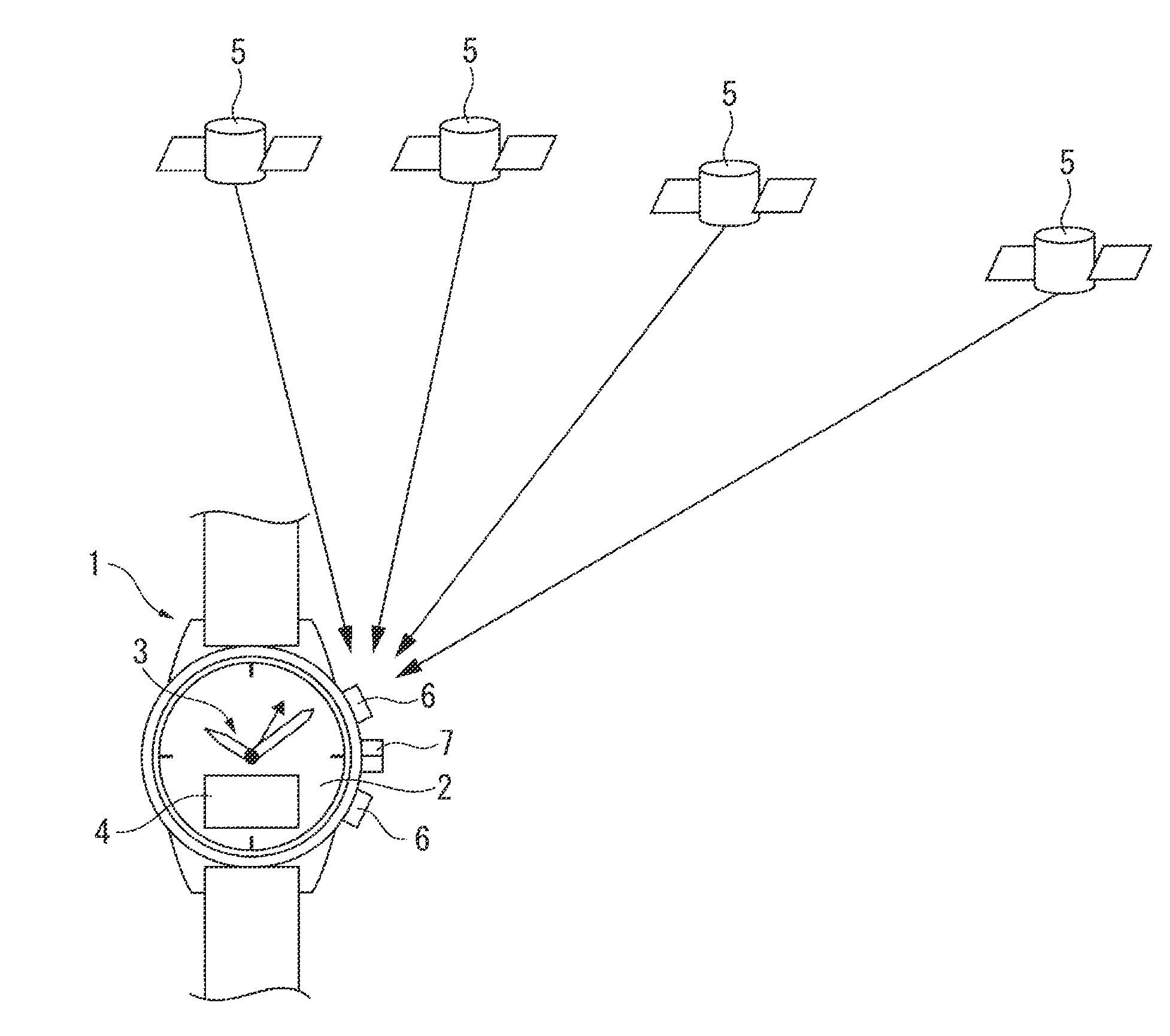
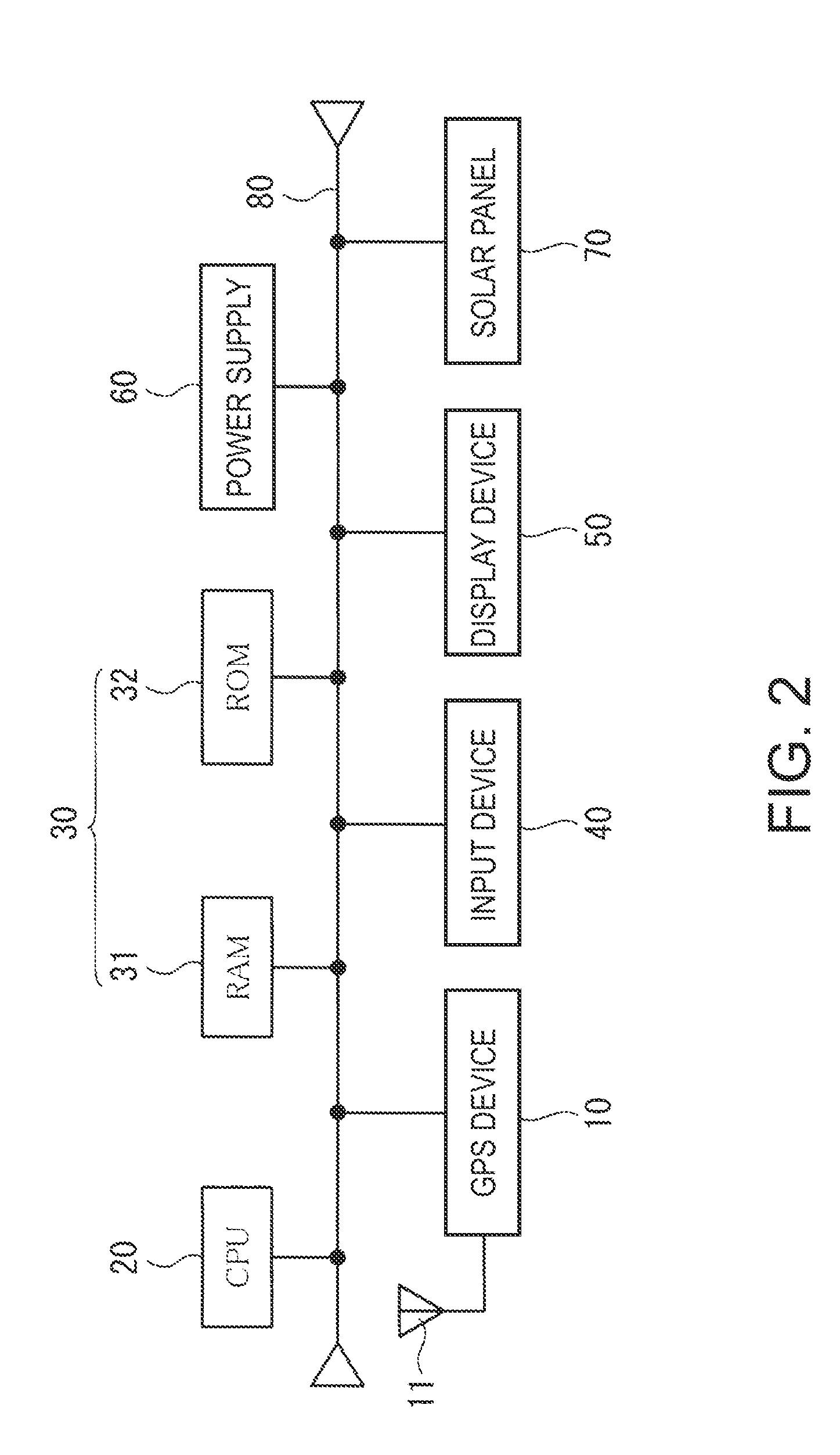
[0081]FIG. 1 is a schematic diagram showing a wristwatch with a GPS satellite signal reception device 1 (referred to below as a GPS wristwatch 1) as an example of an electronic timepiece according to the present invention. FIG. 2 shows the main hardware configuration of the GPS wristwatch 1.
[0082]As shown in FIG. 1, the GPS wristwatch 1 has a time display unit including a dial 2 and hands 3. A window is formed in a part of the dial 2, and a display 4 such as an LCD panel is located in this window.
[0083]The hands 3 include a second hand, minute hand, and hour hand, and are driven through a wheel train by means of a stepping motor.
[0084]The display 4 is typically a LCD unit, for example, and is used for displaying messages in addition to positioning information such as the longitude and latitude or a city name.
[0085]The GPS wristwatch 1 receives satellite signals from a plurality of GPS satellites 5 orbiting the Earth on fixed orbits in space and acquires satellite time information to...
embodiment 2
[0158]A second embodiment of the invention is described next with reference to the flow chart in FIG. 10.
[0159]Note that the circuit configuration of the GPS wristwatch 1 according to the second embodiment of the invention is the same as in the first embodiment, and further description thereof is thus omitted.
[0160]The second embodiment of the invention first checks if a reception request was asserted (S41). A reception request is a signal requesting the reception control unit 21 to start the reception process, and is output when the user manually starts the reception process or when a predetermined reception time arrives.
[0161]If a reception request is detected, the decision unit 211 determines if power generation is greater than or equal to a first power generation evaluation threshold value (S42). This first power generation evaluation threshold value may be a threshold value for determining whether the current location is outdoor during the day or is indoor, and can therefore be...
embodiment 3
[0172]A third embodiment of the invention is described next with reference to the flow chart in FIG. 11.
[0173]This third embodiment differs from the foregoing first embodiment only in that the reception mode is selected based on whether or not power generation is greater than or equal to a power generation evaluation threshold value as shown in step S51 in FIG. 11. Other aspects of the configuration and process according to this embodiment of the invention are the same as the first embodiment, and further description thereof is omitted.
[0174]More specifically, if as described in the first embodiment the set reception interval time has passed since the last time information was received (S11 returns Yes), the power output is greater than or equal to a power generation threshold value (S12 returns Yes), and power generation greater than or equal to the power generation threshold value has continued for at least an outdoor determination time (S13 returns Yes), whether or not the power ...
PUM
 Abstract
Description
Claims
Application Information
 - R&D
- Intellectual Property
- Life Sciences
- Materials
- Tech Scout
- Unparalleled Data Quality
- Higher Quality Content
- 60% Fewer Hallucinations
Browse by: Latest US Patents, China's latest patents, Technical Efficacy Thesaurus, Application Domain, Technology Topic, Popular Technical Reports.
© 2025 PatSnap. All rights reserved.Legal|Privacy policy|Modern Slavery Act Transparency Statement|Sitemap|About US| Contact US: help@patsnap.com


