
Airbag-equipped steering wheel device

a technology of steering wheel and airbag, which is applied in the direction of acoustic signal devices, vehicle components, pedestrian/occupant safety arrangements, etc., can solve the problems of increasing the number of components, complicating the structure for engaging and disengaging elastic wires, so as to achieve the effect of easy unfastening and reducing the size of a spa

Inactive Publication Date: 2010-09-02
TOYODA GOSEI CO LTD
View PDF10 Cites 44 Cited by
  • Summary
  • Abstract
  • Description
  • Claims
  • Application Information

AI Technical Summary

Benefits of technology

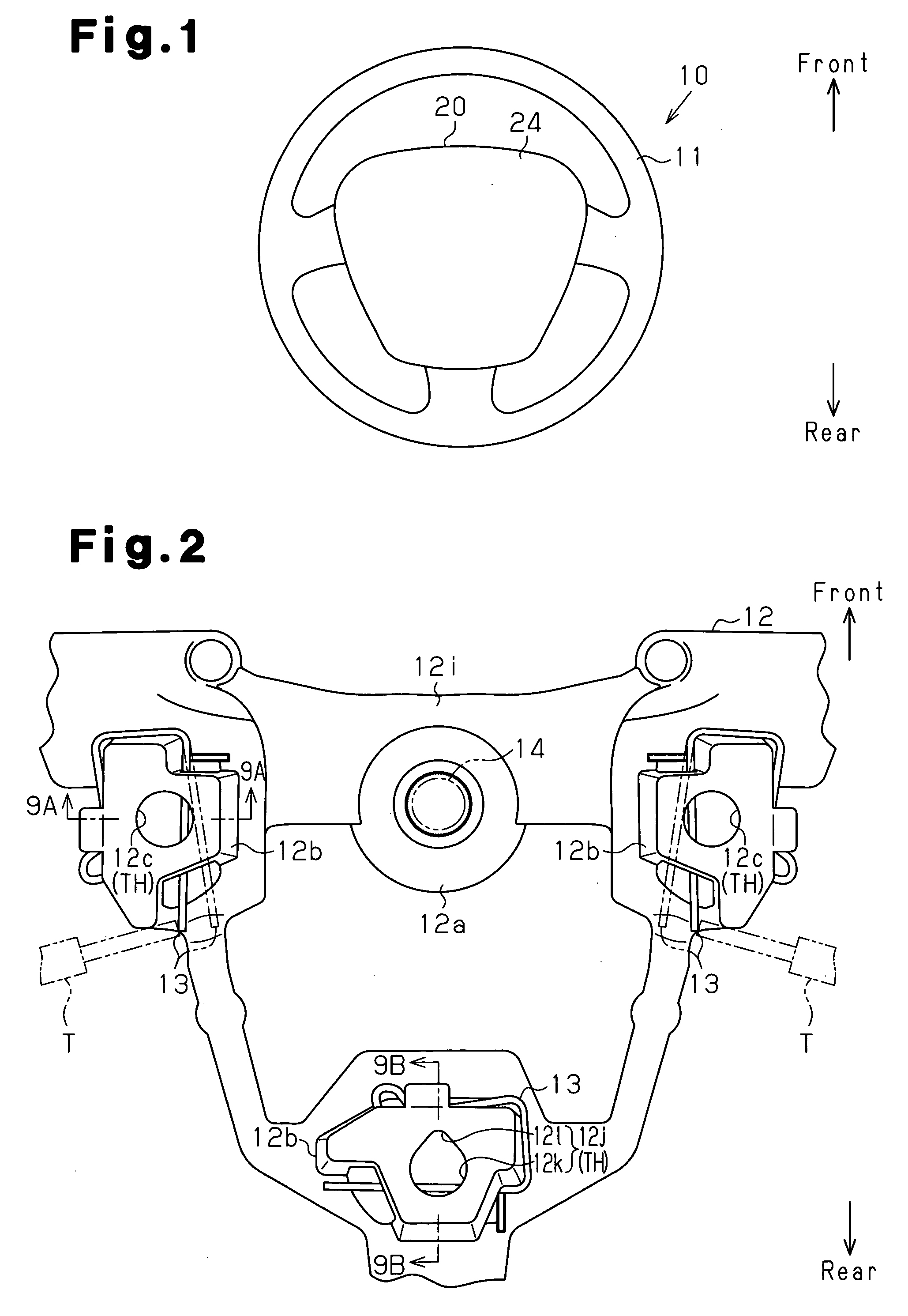
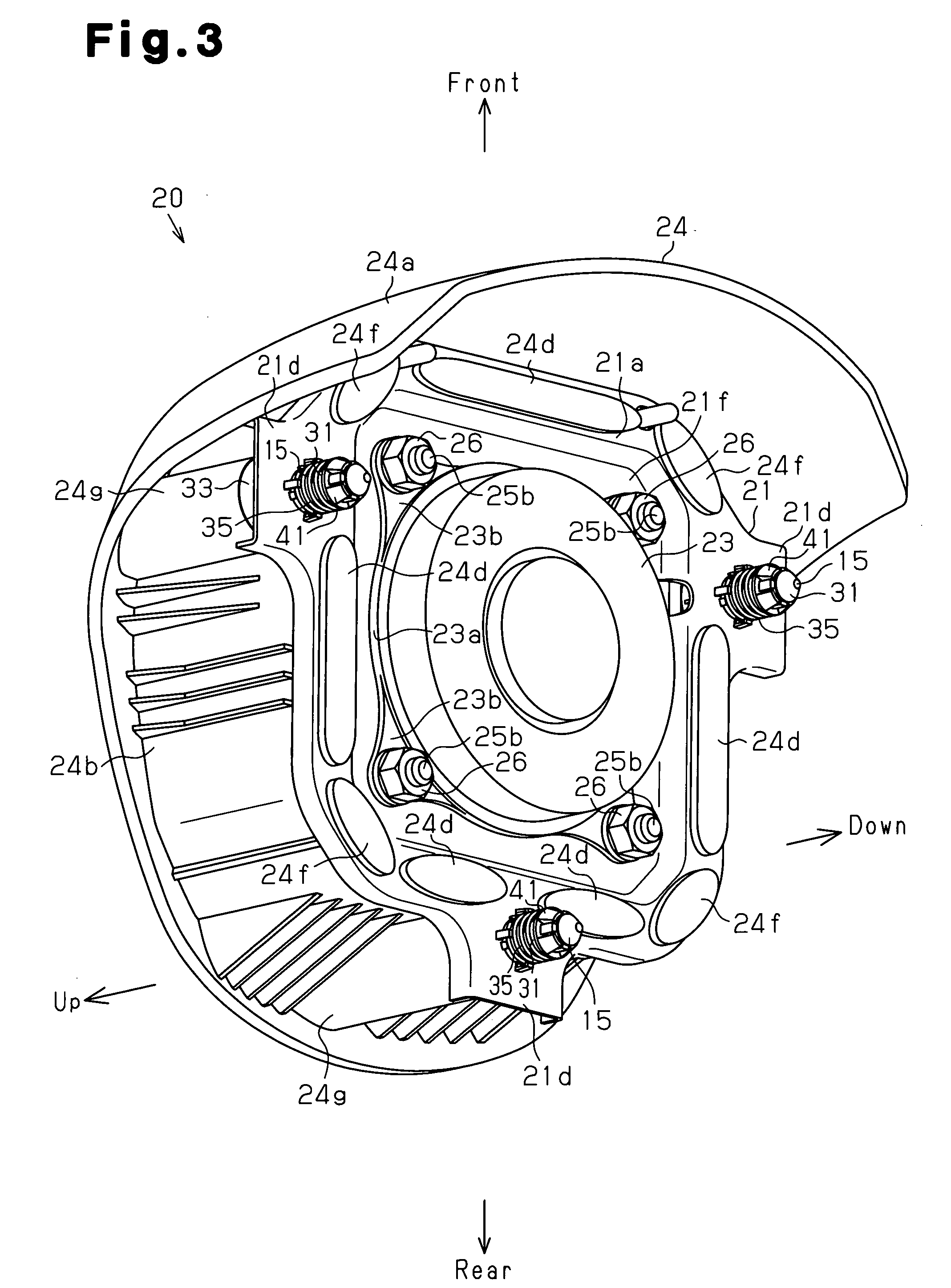
The present invention provides an airbag-equipped steering wheel that reduces the space needed for the elastic members and allows for easy unfastening of multiple horn switch mechanisms. The metal core has through holes, and the airbag device is located above the through holes with a bag holder, pad portion, airbag, and inflator. The elastic members are located below the through holes, and the horn switch mechanisms are located between the airbag device and the metal core. Each horn switch mechanism corresponds to a through hole. When the airbag device is pressed down, any of the horn switch mechanisms activates a horn device. The support members of the horn switch mechanisms are inserted into the through holes and engage with elastic members. The through holes have normal through holes and special through holes with an inclination permitting portion. The inclination permitting portion allows the support member to be inclined about the elastic member only when the elastic members are disengaged from the support members in all the normal through holes.

Problems solved by technology

This complicates the structure and increases the number of components.
This complicates the structures for engaging and disengaging of the elastic wire.
On the other hand, as the functionality of steering wheels has been improved, it has become difficult to provide a sufficient space in the steering wheel.
This makes the removal of the elastic members 56 troublesome.

Method used


Image

  • Airbag-equipped steering wheel device
  • Airbag-equipped steering wheel device
  • Airbag-equipped steering wheel device

Examples


Embodiment Construction

[0041]An airbag-equipped steering wheel according to one embodiment of the present invention will now be described with reference to FIGS. 1 to 18. The steering wheel is used in a vehicle. Hereinafter, the advancing direction of the vehicle will be referred to as the front of the vehicle, and the widthwise direction of the advancing vehicle will be referred to as the left-right direction of the vehicle. The steering wheel includes a steering wheel main body, an airbag device, and horn switch mechanisms.

[0042]As shown in FIGS. 1 and 2, a steering wheel 10 includes a steering wheel main body 11, which is held by the driver. An airbag device (airbag module) 20 is installed at a center of the steering wheel main body 11. The steering wheel main body 11 includes a metal core 12, which is formed by the framework of the steering wheel 10. The metal core 12 is made of iron, aluminum, magnesium, or an alloy thereof. The metal core 12 is fixed to a steering shaft 14 with a boss portion 12a.

[...


PUM


Abstract

In an airbag-equipped steering wheel, a plurality of horn switch mechanisms assembled to a bag holder each have a securing pin, which is inserted into a corresponding one of through holes formed in a metal core. A clip is engaged with a locking groove of each securing pin, so that each horn switch mechanism is fastened to the metal core. The through holes include one or more normal through holes that restrict inclination of the corresponding securing pins, and a special through hole that has an inclination permitting portion. The inclination permitting portion permits the corresponding securing pin to be inclined about the corresponding clip 13 serving as a fulcrum. In the special through hole, the securing pin is permitted to be inclined about the clip serving as a fulcrum only when the clips are disengaged from the securing pin in all the normal through holes.

Description

BACKGROUND OF THE INVENTION[0001]The present invention relates to a steering wheel having an airbag device for protecting an occupant from an impact applied from the front of a vehicle.[0002]Japanese Laid-Open Patent Publication No. 2004-284414 discloses such a steering wheel, which includes a metal core, an airbag device, and a plurality of horn switch mechanisms. The metal core consists of the framework of the steering wheel. The airbag device is formed by assembling a pad portion, an airbag, and an inflator into a bag holder. The airbag device is arranged substantially above the metal core. The horn switch mechanisms are located between the airbag device and the metal core. When the airbag device is pressed down, the horn switch mechanisms activate the horn device.[0003]When an impact is applied to a vehicle having the steering wheel from the front, the inflator of the airbag device discharges inflation gas to inflate the airbag. The inflation of the airbag breaks the pad portion...

Claims


Application Information

Patent Timeline
Patent Type & Authority Applications(United States)
IPC IPC(8): B60R21/16
CPCB60R21/2037B60Q5/003
Inventor SASAKI, KENJIHIROSE, OSAMUSUZUKI, NORIOIIDA, HITOSHIBANNO, YOSHITERUOKADA, TOMOKIASANO, MASAKAZU
Owner TOYODA GOSEI CO LTD
Learn More