
Selective control of wireless initiation devices at a blast site

Active Publication Date: 2010-08-26
ORICA EXPLOSIVES TECH PTY LTD
View PDF1 Cites 16 Cited by
  • Summary
  • Abstract
  • Description
  • Claims
  • Application Information

AI Technical Summary

Benefits of technology

[0038]“Wireless detonator assembly”—refers in general to an assembly encompassing a detonator, most preferably an electronic detonator (typically comprising at least a detonator shell and a base charge) as well as wireless signal receiving and processing means to cause actuation of the base charge upon receipt by said wireless detonator assembly of a wireless signal to FIRE from at least one associated blasting machine. For example, such means to cause actuation may include signal receiving means, signal processing means, and a firing circuit to be activated in the event of a receipt of a FIRE signal. Preferred components of the wireless detonator assembly may further include means to wirelessly transmit information regarding the assembly to other assemblies or to a blasting machine, or means to relay wireless signals to other components of the blasting apparatus. Other preferred components of a wireless detonator assembly will become apparent from the specification as a whole. The expression “wireless detonator assembly” may in very specific embodime

Problems solved by technology

Nonetheless, the development of wireless blasting systems, and components thereof, presents a formidable technological challenge.
In just one example, selective control and firing of wireless detonators in pre-determined groups (as discussed above in the context of wired blasting systems) is not simple to achieve since there are no harness wires present for selective connection of the detonators.

Method used


Image

  • Selective control of wireless initiation devices at a blast site
  • Selective control of wireless initiation devices at a blast site
  • Selective control of wireless initiation devices at a blast site

Examples


example 1

Protocol Design Options for Selective Blasting in Groups

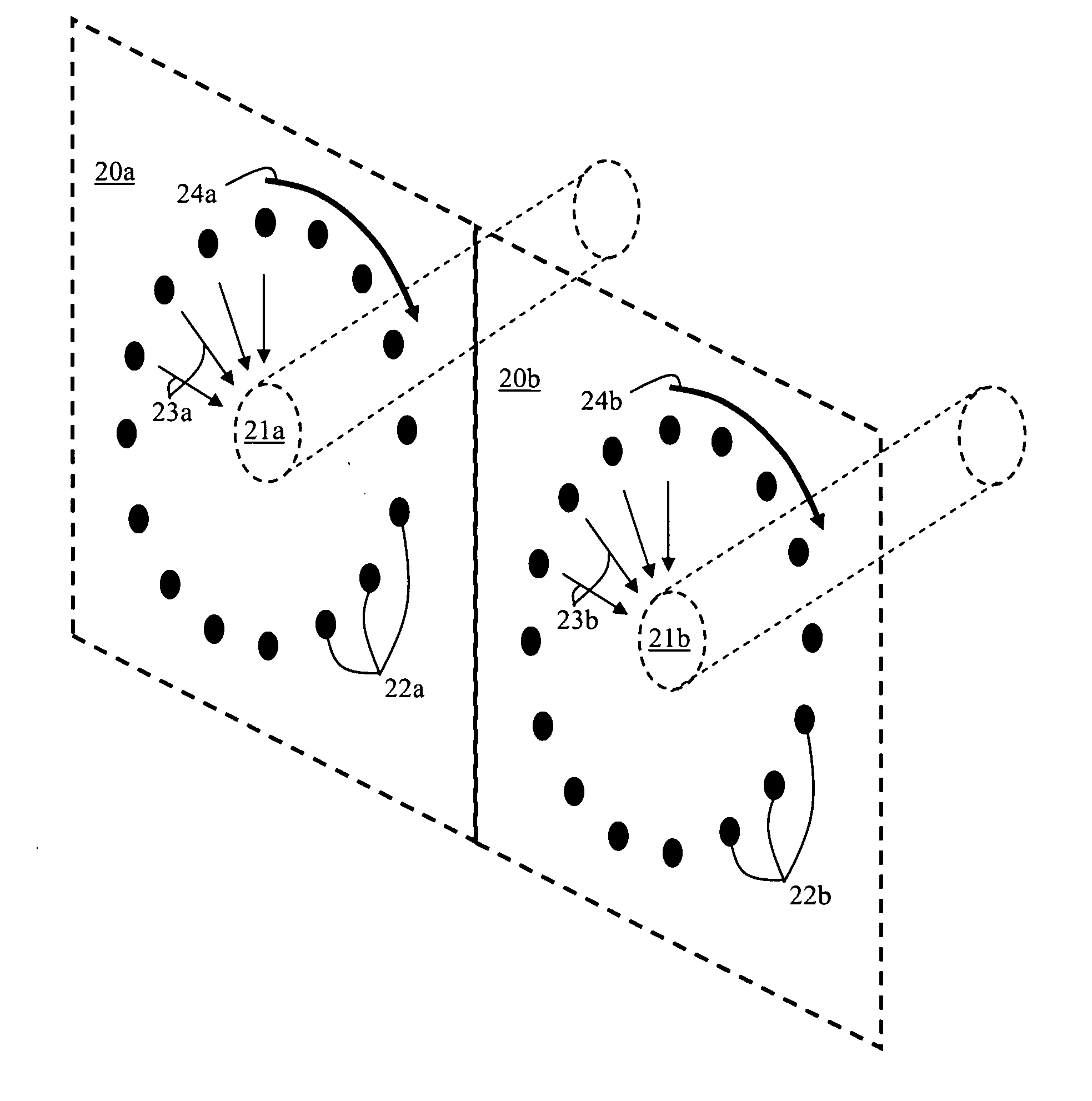
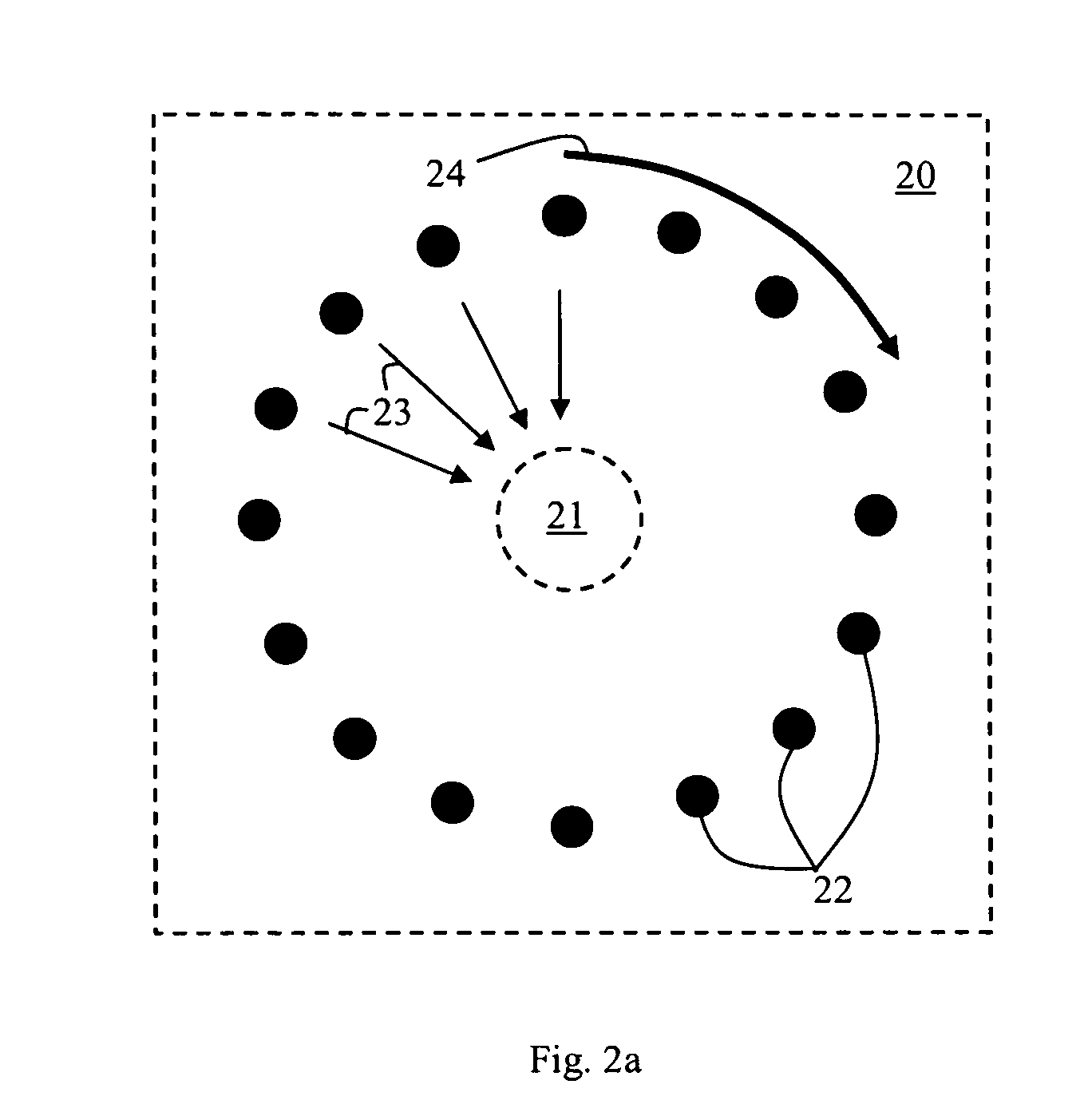
[0090]In accordance with selected embodiments of the present invention, a blasting apparatus that employs wireless initiation devices may be established at a blast site. As discussed, the wireless initiation devices may take any form, including wireless electronic boosters, or wireless initiation devices optionally including top-boxes. The group identifications may be pre-programmed into the wireless initiation devices prior to placement at the blast site. Therefore, various protocol options are available to program the devices with group identifications, following by selective blasting.

[0091]Typically, during a blasting event each wireless initiation device at the blast site may be contacted several times by an associated communicating device such as a blasting machine. Corresponding wireless signals transmitted to the devices may include, but are not limited to, command signals for:

[0092]STATUS CHECK (to confirm that the devi...

example 2

Surface Blasting of Wireless Initiation Devices in Groups

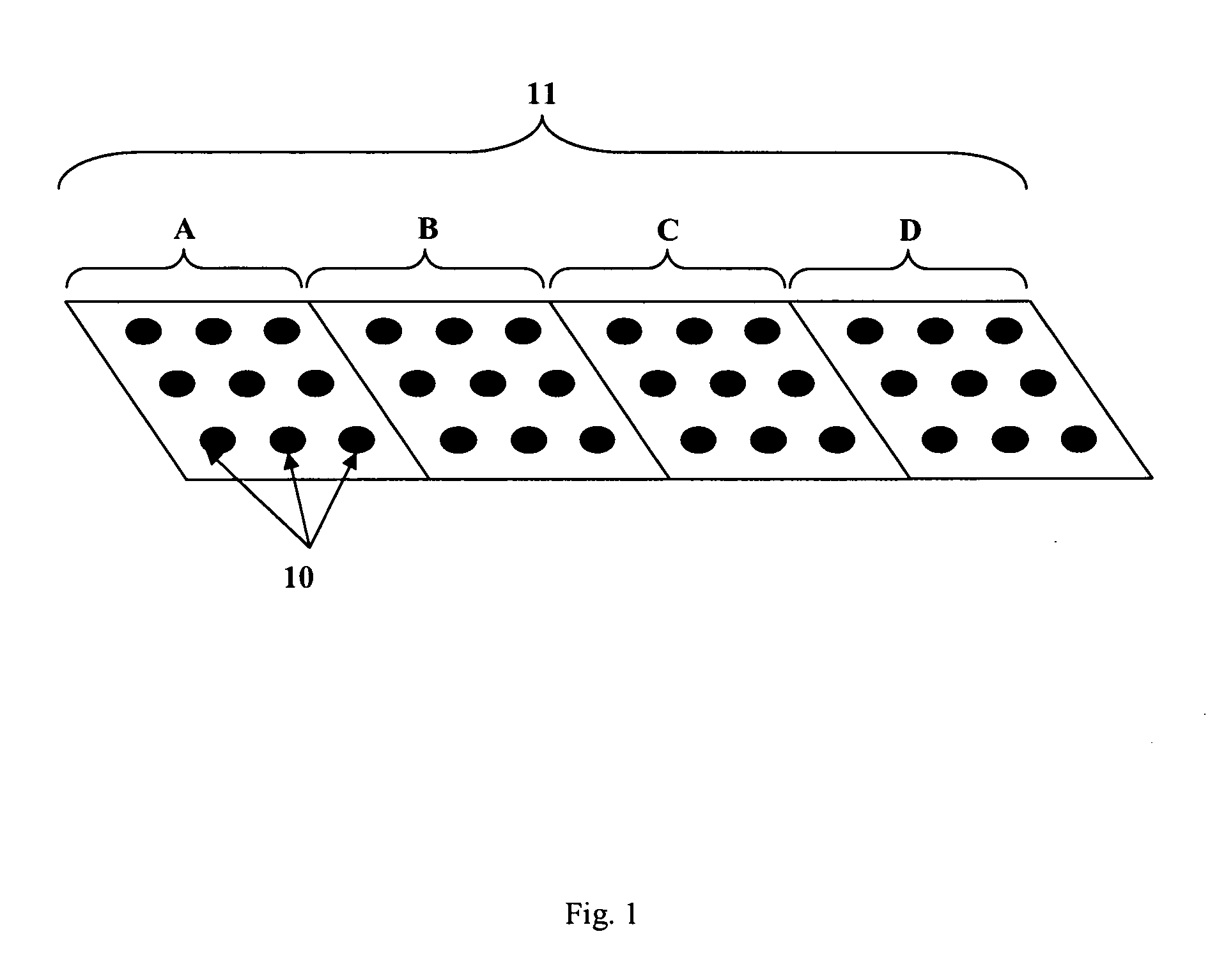
[0112]Certain exemplary embodiments of the methods of the present invention may be applied to surface blasting techniques. Such examples will be described with reference to FIG. 1, which schematically illustrates a perspective view of the surface of an area of ground in which there have been established boreholes 10 established in an area of ground 11. The area 11 is divided into four sections A, B, C, and D each containing a plurality of boreholes, each borehole containing a wireless initiation device. Optionally a top-box (not shown) of the type that is known in the art may extend near to or above the surface of the ground at each borehole, with communication means extending from each top-box to other components of a wireless initiation device including a detonator (not shown) located down the borehole.

[0113]The methods of the present invention permit selective control and initiation of the wireless initiation devices in gro...

example 3

Clock Calibration of Wireless Electronic Boosters Positioned Underground

[0117]The methods of the present invention may be applied to both surface mining and underground mining techniques. For example, the methods of the invention may be applied to wireless electronic boosters such those disclosed for example WO2007 / 124539 published Nov. 8, 2007, which is incorporated herein by reference. Techniques have been developed for clock calibration of such wireless electronic boosters when positioned underground for underground blasting, even though such calibration signals must be transmitted through-rock (see for example WO2007 / 124538 published Nov. 8, 2007, which is also incorporated herein by reference). Such complex signals are difficult to transmit successfully and without interference through rock. However, it should be noted that even calibration signals transmitted through-rock (or indeed other wireless command signals transmitted through rock) are amenable to being ‘tagged’ by a gr...


PUM


Abstract

Disclosed herein are methods for selective control of groups of wireless initiation devices such as wireless electronic boosters at a blast site. Such methods may be applied to a wide variety of blasting techniques that would benefit from the use of wireless control and initiation of explosive charges at the blast site.

Description

CROSS-REFERENCE TO RELATED APPLICATION[0001]This application claims the benefit of Provisional Application No. 61 / 147,816, filed Jan. 28, 2009, the entire contents of which is hereby incorporated by reference in this application.FIELD OF THE INVENTION[0002]The invention relates to the field of blasting for mining, and the control of detonators at a blast site. More specifically, the invention relates to the control of detonators and detonator assemblies via wireless communication.BACKGROUND TO THE INVENTION[0003]The efficient fragmentation and breaking of rock by means of explosive charges demands considerable skill and expertise. In most mining operations explosive charges, including boosters, are placed at predetermined positions near or within the rock, for example within boreholes drilled into the rock. The explosive charges are then actuated via detonators having predetermined time delays, thereby providing a desired pattern of blasting and rock fragmentation. Traditionally, si...

Claims


Application Information

Patent Timeline
IPC IPC(8): F23Q21/00
CPCF42D1/02F42D3/04F42D1/05
Inventor MCCAAN, MICHAEL JOHNSTEWART, RONALD F.
Owner ORICA EXPLOSIVES TECH PTY LTD
Learn More