Method for mutli-stage spatial sampling with multiple criteria

a spatial sampling and multiple criteria technology, applied in the field of mutlistage spatial sampling with multiple criteria, to achieve the effect of convenient transport on si

Active Publication Date: 2010-08-19
TUFTS UNIV
View PDF8 Cites 9 Cited by
  • Summary
  • Abstract
  • Description
  • Claims
  • Application Information

AI Technical Summary

Benefits of technology

[0016]The computational processes of the invention may be designed into software or into memory of a computer device. This software is loaded into a computer or computational dev...

Problems solved by technology

Therefore, the sampling design problem...

Method used


Image

  • Method for mutli-stage spatial sampling with multiple criteria
  • Method for mutli-stage spatial sampling with multiple criteria
  • Method for mutli-stage spatial sampling with multiple criteria

Examples


Embodiment Construction

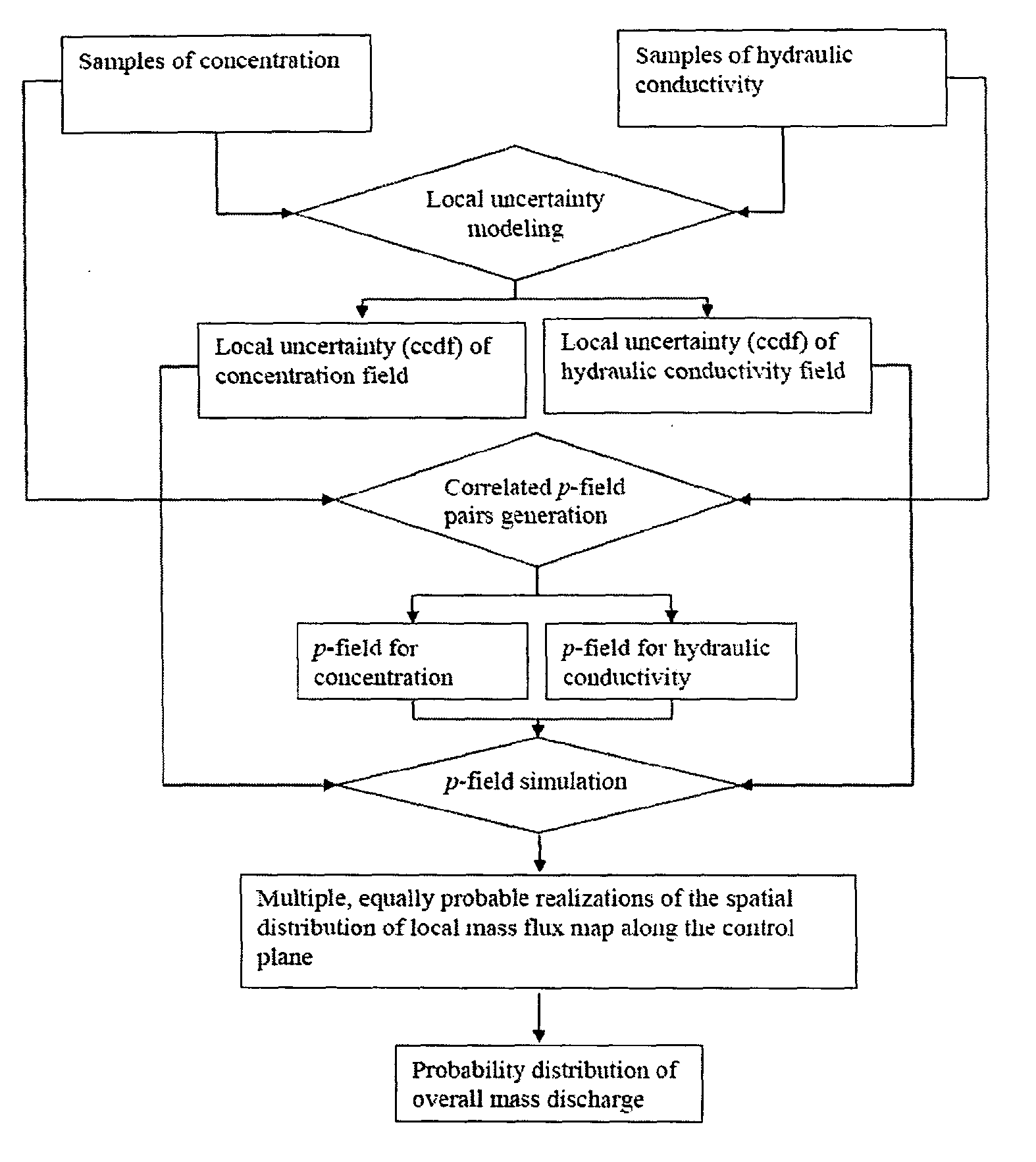
[0028]Certain exemplary embodiments of the present invention are described below. The invention is not limited to these embodiments. The spatial sampling design concentrates sampling effort on uncertain locations of the hot spot areas (e.g., areas of high contaminant concentration) in a plane (e.g., contamination plane) thereby significantly improving sampling efficiency. An initial sampling starts the sampling process. In order to maximize the information quality of sample data, the sampling density in the initial stage is kept minimal. For example, nine observations in the initial sampling stage. However, it is contemplated that fewer than nine observations are also possible depending on the situation in the field. It is contemplated that each observation is added one by one, so that the information brought by additional samples is fully used. In this way, every observation represents a sampling stage. For every sampling stage, observations are processed by the geostatistical appr...


PUM


Abstract

The present invention provides a method for implementing a multi-stage spatial sampling strategy to select optimal sampling locations and determine an optimal sampling density for a quantification of mass discharge uncertainty in a field. The present invention also provides systems and methods for estimating probability of a mass discharge in a control plane.

Description

[0001]The present application claims priority to U.S. Provisional Application No. 60 / 874,214 filed Dec. 11, 2006, incorporated herein by reference in its entirety. This invention was made with government support under contract CU-1293 awarded by the Department of Defense Strategic Environmental Research and Development Program. The government has certain rights in the invention.FIELD OF THE INVENTION[0002]The present invention provides a method for implementing a multi-stage spatial sampling strategy to select optimal sampling locations and determine an optimal sampling density for a quantification of mass discharge uncertainty in a field. The present invention also provides systems and methods for estimating probability of a mass discharge in a control plane.BACKGROUND OF THE INVENTION[0003]Contaminant mass discharge across a control plane downstream of a Dense Nonaqueous Phase Liquid (DNAPL) source zone has great potential to serve as a metric for the assessment of the effectivene...

Claims


Application Information

Patent Timeline
IPC IPC(8): G06F17/18G06N5/02
CPCB09C1/00G01N2001/021G01N1/02
Inventor LI, KE BETTYABRIOLA, LINDA M.
Owner TUFTS UNIV
Why Eureka
Try Eureka