
Insertion device with pivoting action

a technology of insertion device and pivoting action, which is applied in the direction of catheters, trocars, infusion needles, etc., can solve the problems of achieve the effects of reducing infection and contamination risk, facilitating administration and handling, and improving user friendliness

Active Publication Date: 2010-08-12
UNOMEDICAL AS
View PDF103 Cites 100 Cited by
  • Summary
  • Abstract
  • Description
  • Claims
  • Application Information

AI Technical Summary

Benefits of technology

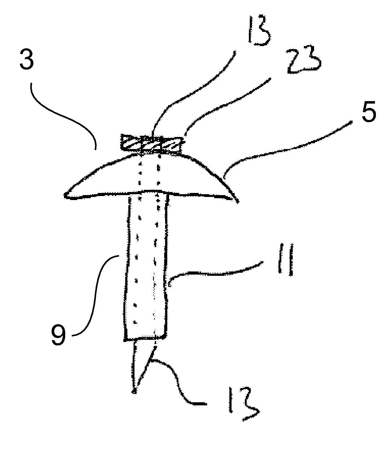
[0009]The current invention provides an insertion device, where the penetrating device, such as needle or cannula or both, are not visible prior, during and after insertion of the medical device, whereby administration and handling is drastically facilitated, and user friendliness is improved. Further this device reduces the risk of infections and contaminations, due to the absence of an exposed penetrating device. When applicable, the medical device's insertion needle is retracted into the housing of the insertion device, thus facilitating handling and disposing of the medical device in question.
[0015]According to one embodiment the guiding means comprise one or more guiding slots. These guiding slots can be provided on the lower section where the guiding slots can be parallel to the direction of insertion, and are of the same length or longer than the length of said longitudinal movement. The guiding slots can be encompassing the shaft, and restrict the length of the longitudinal movement of the shaft and the lower section.

Problems solved by technology

Further this device reduces the risk of infections and contaminations, due to the absence of an exposed penetrating device.

Method used


Image

  • Insertion device with pivoting action
  • Insertion device with pivoting action
  • Insertion device with pivoting action

Examples


Embodiment Construction

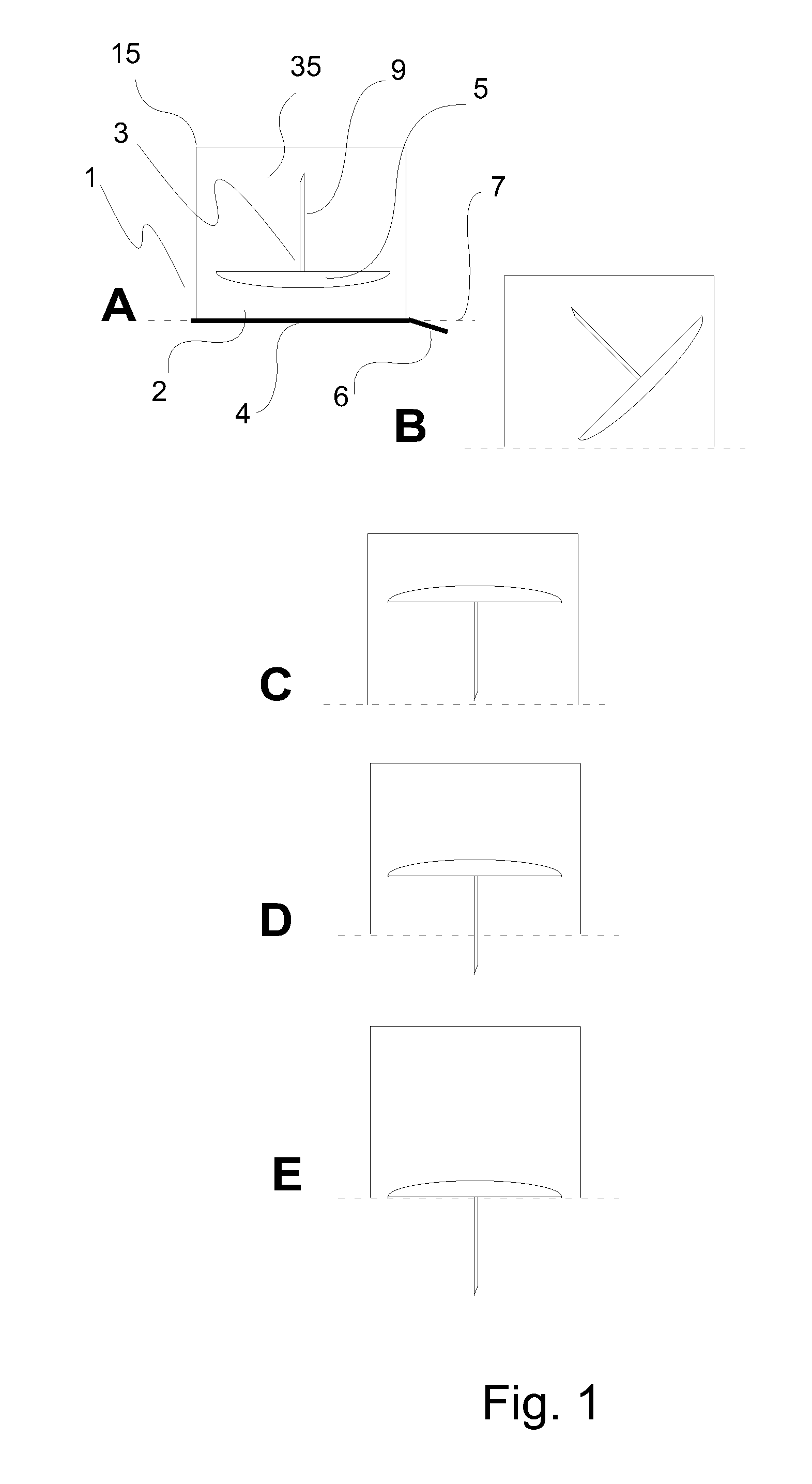
[0042]FIG. 1 shows an insertion device 1, and illustrates different positions of a medical device 3 within the main cavity 35 of the insertion device 1; said medical device 3 comprises a penetrating member 9, according to the current invention. The main cavity 35 is defined as the volume within the housing 15 of the insertion device 1 and a bottom plane 7, illustrated by a stippled line. The main cavity 35 is sufficiently dimensioned, in width, height and diameter, and optionally flexible and / or variable in size to encompass a medical device 3 comprising a penetrating member 9, and to allow for one or more rotations and / or pivoting movement, and optionally, one or more longitudinal movements (FIG. 1).

[0043]The insertion device according to the invention comprises an opening 2 towards the bottom plane 7 of the housing 15. Said opening is as wide as, or wider than the body 5 of the medical device 3 to be inserted. The embodiment of an insertion device 1 shown in FIG. 1 comprises an op...


PUM


Abstract

The invention concerns an insertion device for inserting a medical device into the subcutaneous or intramuscular area of a patient. More specifically, this invention relates to an insertion device comprising pivoting and guiding means for moving a penetrating member from a position, where the penetrating member is not pointing into the direction of insertion, to a position, where the penetrating member is pointing into the direction of insertion. The inserter device comprises a housing (15) encompassing a penetrating member (9), said housing comprising a top section (14) and a lower section (16), wherein said insertion device (1) comprises pivoting means (27, 31, 41, 43) and guiding means (10, 19, 16s, 31s, 18s) providing one or more pivoting movement(s) of the penetrating member (9) from a first position, where the penetrating member (9) is not pointing into the direction of insertion, to a second position, where the penetrating member (9) is aligned with the direction of insertion, to a third position, where the penetrating member (9) protrudes the housing (15) and the penetrating member (9) is aligned in the direction of insertion. The guiding means (10, 19, 16s, 31s, 18s) are adapted to provide a longitudinal movement of the penetrating member (9) from the second to the third position.

Description

TECHNICAL FIELD OF THE INVENTION[0001]The invention concerns an insertion device for inserting a medical device into the subcutaneous or intramuscular area of a patient. More specifically, this invention relates to an insertion device comprising pivoting and guiding means for moving a penetrating member from a position, where the penetrating member is not pointing into the direction of insertion, to a position, where the penetrating member is pointing into the direction of insertion.BACKGROUND OF THE INVENTION[0002]Insertion devices, also called injectors, are commonly used in the medical field for inserting medical devices such as infusion sets and the like, in a semi-automated fashion through the skin of a patient.[0003]EP 1 011 785 relates to an injector for a subcutaneous infusion set, EP 1 044 028 concerns an insertion device for an insertion set.[0004]EP 1 502 613 relates to an inserter device for inserting a penetrating member into the subcutaneous area of a patient. The pene...

Claims


Application Information

Patent Timeline
IPC IPC(8): A61B17/34
CPCA61M5/158A61M2005/1585A61M2005/1581A61M25/0612
Inventor GYRN, STEFFEN
Owner UNOMEDICAL AS
Learn More