
Liquid crystal shutter glasses

a technology of liquid crystal shutters and liquid crystals, applied in the direction of spectacles/goggles, polarising elements, instruments, etc., can solve the problems of limited display light from the display apparatus, insufficient transmission/shielding contrast, and difficulty in maintaining a specific angle between the polarization plane of the polarization filter of the display apparatus, so as to reduce flicker

Active Publication Date: 2010-08-12
NEC CORP
View PDF8 Cites 29 Cited by
  • Summary
  • Abstract
  • Description
  • Claims
  • Application Information

AI Technical Summary

Benefits of technology

[0012]The glasses described in Patent Literature 4 are polarization glasses with no shutter function. They have a polarization filter on a part of the spectacle lens in order to prevent peek through the glasses. They are irrelevant to the flickering due to ambient light the observer may sense. The glasses described in Patent Literature 5 use polarization spectacle lenses having a transmission part for easy viewing of things other than the displayed image. In Patent Literature 8, the upper half of the lens consists of a liquid crystal light modulation layer for the same reason. Both glasses are intended for easy viewing of the surroundings, not the displayed image, and irrelevant to the flickering due to ambient light the observer may sense like the glasses in Patent Literature 4. In the glasses described in Patent Literature 6, an electronic shutter element is embedded in the lens for improved weather resistance of the electronic shutter element and combined use with vision correction glasses. These glasses are irrelevant to the flickering due to ambient light the observer may sense. Patent Literature 7 has no description regarding the flickering due to ambient light the observer may sense.
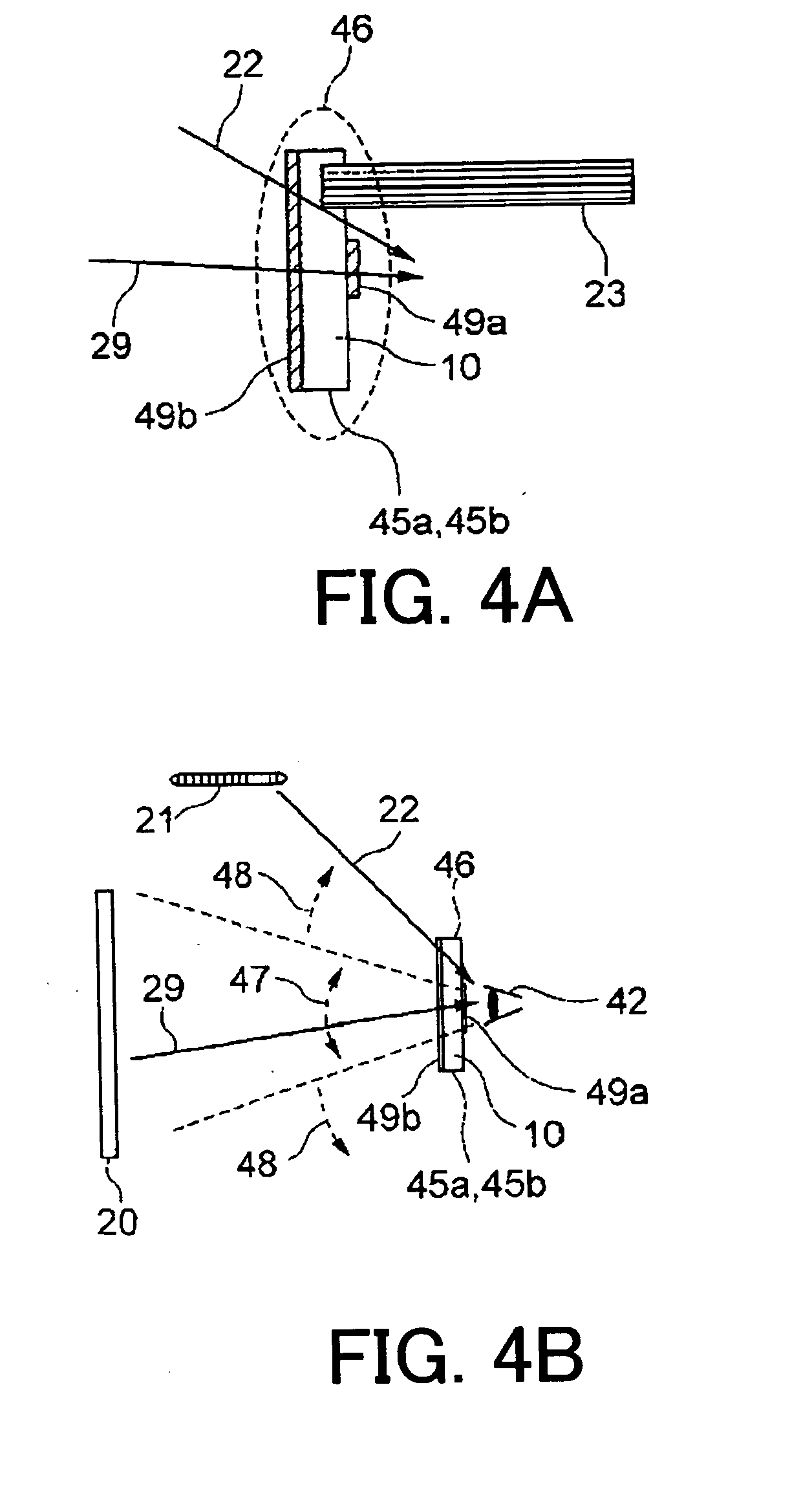
[0014]As shown in FIG. 16B, the observer 42 observes a field sequential display unit 20 within a central view field 47. The transmission / shielding of the liquid crystal shutter 45 can be controlled in sync with the display screen of the field sequential display unit 20 so that the display light 29 from the field sequential display unit 20 is transmitted / shielded. On the other hand, ambient light 22 from a peripheral view field 48 such as light from a fluorescent lamp 21 reaches the observer 42 without passing through the area of the effective lens region 46 where the liquid crystal shutter 45 is formed. Therefore, the ambient light 22 enters the eyes of the observer 42 regardless of the transmission / shielding of the liquid crystal shutter part 45, thereby reducing flickering. However, the liquid crystal shutter glasses having the effective lens region 46 partly formed by the liquid crystal shutter part 45 allows the ambient light 22 to enter the eyes of the observer 22 as it is. Here, a new problem is that the pupils of the observer 42 contract and the observer 42 feels that the display on the field sequential display unit is dark.
[0015]The purpose of the present invention is to provide liquid crystal shutter glasses that prevent the observer from sensing any flickering and allow the observer to feel that the display on the field sequential display unit is bright.
[0017]The liquid crystal shutter glasses of the present invention has the effect that the observer of a display apparatus sense no flickering and feels that the display on the field sequential display unit is bright when he / she observes the display apparatus with the liquid crystal shutter glasses.

Problems solved by technology

Therefore, the display light from the display apparatus has to be polarized light; namely, the display light from the display apparatus is restricted.
This is because sufficient transmission / shielding contrast is not obtained if the angle deviates from the specific angle.
However, it is difficult to maintain a specific angle between the polarization plane of the polarization filter of the display apparatus and the polarization plane of the liquid crystal shutter glasses because the observer does not always face the display apparatus squarely or the observer may lean his body or the glasses may be tilted.

Method used


Image

  • Liquid crystal shutter glasses
  • Liquid crystal shutter glasses
  • Liquid crystal shutter glasses

Examples


Embodiment Construction

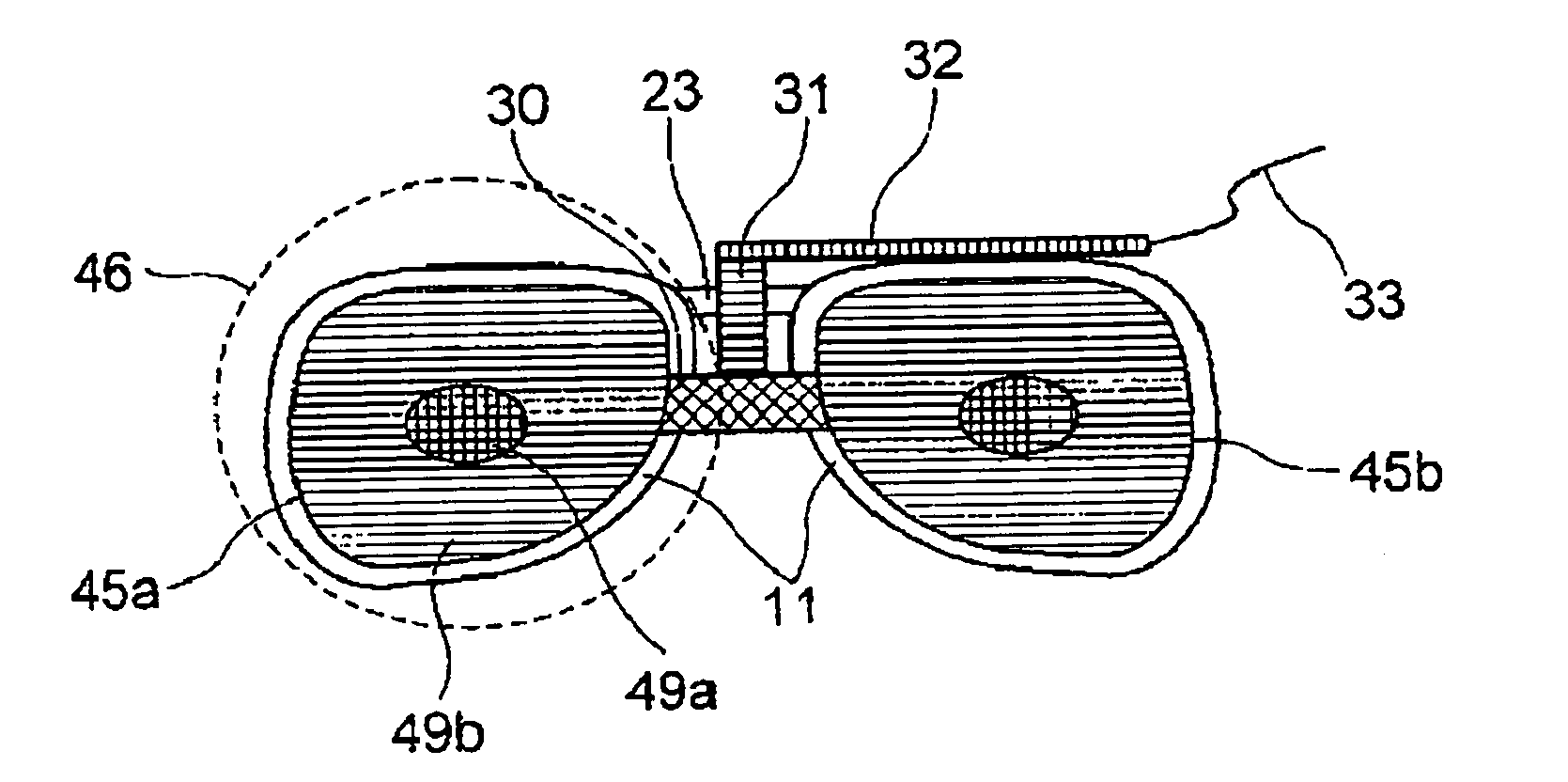
[0035]Embodiments of the present invention will be described in detail hereafter with reference to the drawings. For easy understanding, the same components are referred to by the same reference numbers throughout the figures. FIG. 1 is a front view of the liquid crystal shutter glasses according to an embodiment of the present invention when it is attached to ordinary glasses. The liquid crystal shutter glasses have liquid crystal shutters 45 including a right-eye liquid crystal shutter 45a and a left-eye liquid crystal shutter 45b, a signal receiver 30, and a fixture (support) 31. The liquid crystal shutter glasses have the liquid crystal shutters 45a and 45b within the view angle (effective lens region) 46 of the observer 42 when he / she observes through spectacle lenses 11.

[0036]The liquid crystal shutters 45a and 45b each have an effective shutter region in which the transmission or shielding of incident light is controllable and a light attenuation region positioned outside the...


PUM


Abstract

A liquid crystal shutter glasses comprises a liquid crystal shutter placed within the view angle of the observer of a display apparatus wherein the liquid crystal shutter has an effective shutter region in which the transmission or shielding of incident light is controllable and a light attenuation region positioned outside the effective shutter region for attenuating incident light.

Description

TECHNICAL FIELD[0001]The present invention relates to liquid crystal shutter glasses and more specifically to liquid crystal shutter glasses in which the transmission / shielding is controlled in sync with the display screen of a display unit observed by the observer.BACKGROUND ART[0002]One of the display systems combining a field sequential display unit and liquid crystal shutter glasses is a three-dimensional display system. FIG. 13 shows an exemplary three-dimensional display system. For example, the three-dimensional system is comprised of a field sequential display unit (liquid crystal display apparatus) 20 and liquid crystal shutter glasses 41. The liquid crystal display apparatus 20 alternately displays right-eye images and left-eye images. The liquid crystal shutter glasses 41 have a right-eye liquid crystal shutter 41a and a left-eye liquid crystal shutter 41b. The right-eye liquid crystal shutter 41a and left-eye liquid crystal shutter 41b are switched between transmission a...

Claims


Application Information

Patent Timeline
IPC IPC(8): G02B27/22G02F1/1335
CPCG02B5/30G02B27/017G02B27/2264H04N2213/008G02B2027/0134G02C7/101G02F1/133528G02B2027/0118G02B30/24
Inventor SAITOH, GOROHIMAI, MASAOOKUMURA, FUJIO
Owner NEC CORP
Learn More