
Digital camera with asymmetrically configured sensors

a technology of symmetrical configuration and digital camera, which is applied in the direction of picture signal generators, solid-state device signal generators, television systems, etc., can solve the problems of loss of information contained in those photons arriving after the maximum number is reached, and other noise sources of photoreceptors, so as to reduce the loss of light, reduce the cost, and the effect of compactness

Inactive Publication Date: 2010-08-12
WEINSTEIN LARRY R
View PDF3 Cites 54 Cited by
  • Summary
  • Abstract
  • Description
  • Claims
  • Application Information

AI Technical Summary

Benefits of technology

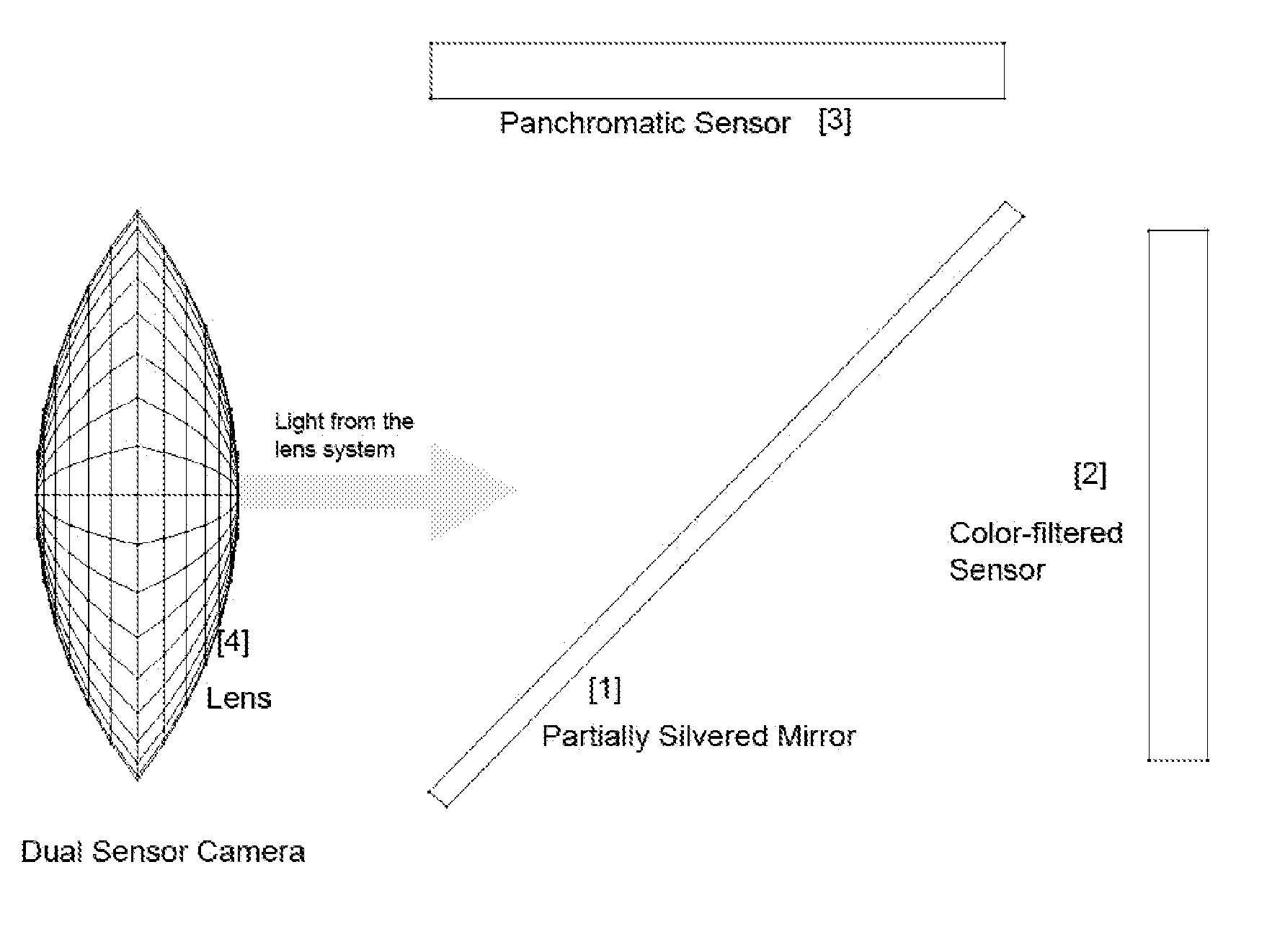
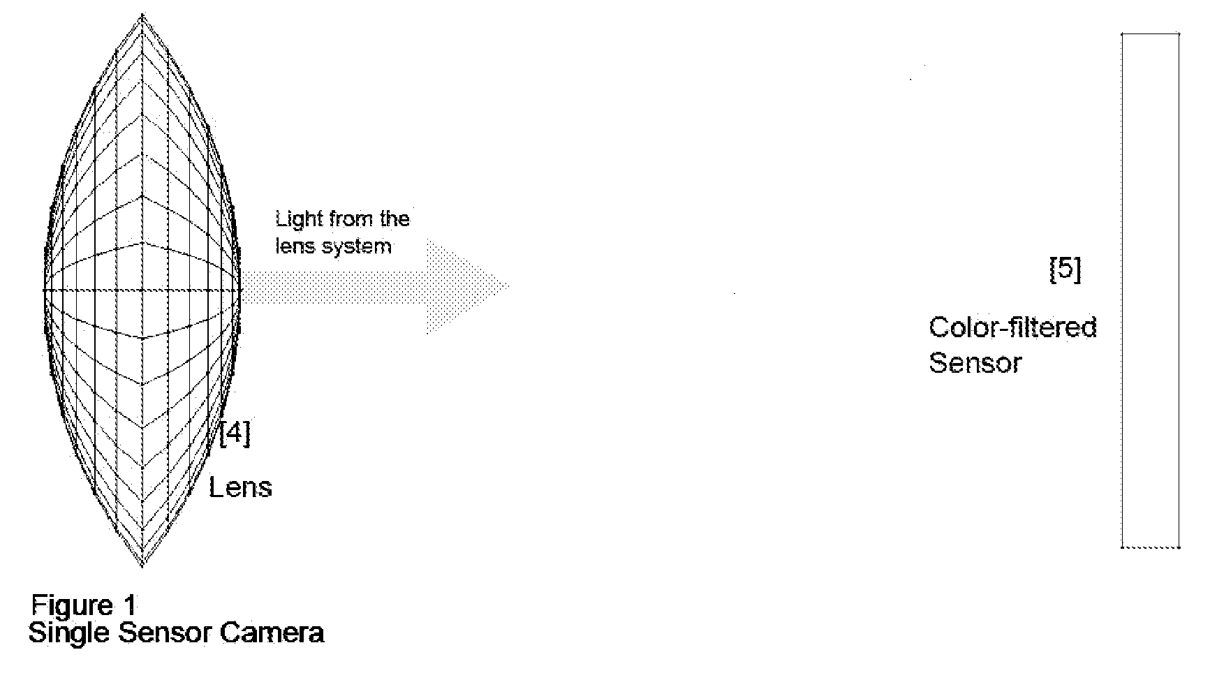
[0028]The invention encompasses a method by which two, asymmetrically configured sensors in a camera may be employed so as to exceed the performance of a single sensor of the same approximate size. The metric of performance is to be a measure of image quality, specifically addressing the issues of noise, resolution, and dynamic range. The primary support systems, especially the lens system, required for the dual sensor instantiation, are no different from those that would be used for one of the sensors alone, hence it is far less costly and more compact than a system that is based upon a larger sensor.
[0041]The current invention takes advantage of elements of human visual perception. The perception of image quality is more sensitive to luminance resolution than color resolution. In the darkest areas of an image, extended dynamic range and reduced noise are more important than resolution. In dark areas of an image, color noise is more objectionable than luminance noise. Increased dynamic range and reduced noise will permit the operation of a camera in reduced levels of light.
[0044]This trade-off is possible due to the use of dissimilar sensors whose photoreceptors differ in size, configuration, and count. By designing the system so that the photoreceptors on the color sensor are significantly larger than those on the panchromatic sensor, the luminance resolution is de-coupled from the color resolution. This, in turn, permits the allocation of light by the splitting element to be designed so as to insure than noise is not increased for either the panchromatic photoreceptors or the color-filtered photoreceptors. The smaller panchromatic photoreceptors insure that the system has a higher resolution than the conventional system throughout almost the entire image, regardless of content (without having higher noise, as just explained.) The larger color-filtered sensors yield a greater system dynamic range.

Problems solved by technology

They also involve weight and cost, both of the sensor and the overall camera system.
These readout and conversion processes have an associated noise factor that cause the final digital value to be other than a perfect representation of the number of photons entering the photoreceptor.
Therefore, the information contained in those photons arriving after the maximum number is reached is lost.
In addition to the readout noise discussed above, there is another source of noise associated with the photoreceptors.
However, at low numbers of photons, this noise factor can be significant.
In conditions of low light, noise can become a significant factor in the quality of the output of the photoreceptors.
Since the number of photons entering each photoreceptor is proportional to the total amount of light striking the sensor divided by the number of photoreceptors (assuming that all are of equal size), increasing the number of photoreceptors on a sensor will result in greater noise under given lighting conditions.
When the dynamic range is small, the camera will not be able to faithfully capture images of scenes that have large variations in light.
However, the detail captured by a more densely packed sensor can be obscured by noise and limited by low dynamic range.
The cost of a solid-state camera sensor goes up exponentially with its size.
Improving one factor at the cost of another may result in a degradation of the image quality.
However, previous designs have not been targeted for use in cameras intended both for high quality still image capture and also high quality video capture.
These earlier designs were dedicated to issues other than the ones addressed here, always making them unsuitable for use in a still image camera.
Because each filter rejects approximately two thirds of the photons arriving at a photo-site, approximately two thirds of the information available is lost.
On the other hand, when an unfiltered photoreceptor detects a photon, the color information is lost.
The physical size of the color separating mechanism is such that constraints are placed on the system with regard to the lens devices that can be used and the size of the sensors.
All such examples result in cameras that produce images that are inferior to those produced by cameras with conventional sensors.
As soon as this point is past, their information becomes invalid.
In this case, the luminance data and chrominance data are each less accurate than the data gathered by a conventional sensor, since they are each based on fewer photons than in the conventional system.
There is no obvious way out of this design dilemma.
These designs either reduce the signal-to-noise ratio, they reduce the dynamic range, or they do both.

Method used


Image

  • Digital camera with asymmetrically configured sensors
  • Digital camera with asymmetrically configured sensors
  • Digital camera with asymmetrically configured sensors

Examples


embodiment example 1

Preferred Embodiment Example 1

[0074]In this example the configuration of the color sensor is partially determined by the desire to maintain compatibility with High Definition video. High Definition video is recorded in a pixel configuration of one thousand nine hundred and twenty by one thousand and eighty (1920×1080). This places a constraint on the configuration of the color sensor. An additional constraint is the desire to maintain compatibility with the photographic standard of a width to height ratio of four to three. It is therefore decided that the color sensor will have a configuration of one thousand nine hundred and twenty by one thousand four hundred and forty (1920×1440). Video images can be produced by mapping a subset of the color sensor's output using a one-to-one correspondence to the desired video output.

[0075]Mindful of these constraints, the following calculations are made.

Color sensor's number of photo-sites=(1920*1440)=2,764,800.

We now must select a conventional...

embodiment example 2

Preferred Embodiment Example 2

[0080]Begin with a 10 “megapixel” (million pixel, and also million photoreceptor), single sensor camera. The camera's sensor is replaced by dual asymmetrically configured sensors, as described by the current invention. Assume the following.[0081]E=4[0082]SA=1[0083]SP=1

Choose, in accordance with the rules of implementation of the current invention:

MA=1(MA>=1)

CA=8.138(CA / MA<=9)

ML=0.66(0.25ML<0.67 and [CP>=MP*3>=1], (2.76>=2.64>1))

[0084]The result is that the output of the camera is still 10 million pixels. However, there is some improvement in the resolution due to the effect of using 10 million panchromatic photoreceptors as opposed to 10 million color-filtered photoreceptors. The signal-to-noise ratio is more than doubled (2.66 times), as is the dynamic range. In photographic terms, this camera has a more than one stop advantage over the original camera, with enhanced resolution. Another advantage is that the color-filtered sensor is in a co...


PUM


Abstract

A method is described by which two, asymmetrically configured sensors, one being panchromatic and the other recording color, may be employed in a digital camera so as to exceed the performance, in terms of signal-to-noise ratio, resolution, and dynamic range, and with regard to visual perception, of a single sensor of the same approximate size.

Description

FIELD OF THE INVENTION[0001]This invention relates to an improved form of digital camera that can be used for still image and video capture.BACKGROUND OF THE INVENTION[0002]The design of a sensor system for a digital camera involves multiple tradeoffs. These include factors affecting the final image quality such as dynamic range, responsiveness in low light environments, resolution, signal-to-noise ratio, and freedom from digital artifacts. They also involve weight and cost, both of the sensor and the overall camera system. These tradeoffs must take into account the changing role of the digital camera. The differentiation between still image and video cameras has largely disappeared. Increasingly, cameras are required to do well in both roles. It is also true that one of the most common types of cameras, the single lens reflex, may soon be eclipsed by cameras that possess electronic viewfinders and real time visual displays of through-the-lens camera views.[0003]The modern digital c...

Claims


Application Information

Patent Timeline
IPC IPC(8): H04N5/235H04N5/225
CPCH04N9/045H04N9/097H04N9/09H04N23/16H04N23/13
Inventor WEINSTEIN, LARRY R.
Owner WEINSTEIN LARRY R
Learn More