
Sun Following Sensor Unit And A Sun Following Apparatus Having The Same Therewith

Inactive Publication Date: 2010-08-05
YOON JOO PYOUNG
View PDF3 Cites 12 Cited by
  • Summary
  • Abstract
  • Description
  • Claims
  • Application Information

AI Technical Summary

Benefits of technology

[0016]In addition, another object of the present invention is to provide a sun tracking sensor unit having a simple whole structure and a low manufacturing and maintenance cost, and a sun tracking apparatus having the sun tracking sensor unit.
[0027]In the present invention, the operation of an east-west driving motor or south-north driving motor is controlled using the intensity of the unbalanced current generated due to the internal resistance unbalance between the two CDS elements corresponding to each other as a signal value, thereby allowing the solar panel to be continuously directed to the sun.

Problems solved by technology

First, since the unit sensors of the sun tracking sensor unit do not sense and track the sunlight having a critical illumination intensity or less, it is impossible to track and collect the sunlight in a cloudy day. Further, when the sun is covered by the clouds for a long time and then reappears therefrom, great confusion is caused in the sun tracking, which additionally requires the manual operation.
In addition, computer equipment is expensive, which operates program for calculating a quantity required in adjusting the angle of a solar panel using signal values received from the sun tracking sensor unit as input data.

Method used


Image

  • Sun Following Sensor Unit And A Sun Following Apparatus Having The Same Therewith
  • Sun Following Sensor Unit And A Sun Following Apparatus Having The Same Therewith
  • Sun Following Sensor Unit And A Sun Following Apparatus Having The Same Therewith

Examples


Embodiment Construction

[0039]Hereinafter, a sun tracking sensor unit and a sun tracking apparatus according to embodiments of the present invention will be described in detail with reference to the accompanying drawings.

[0040]FIG. 1 is a front sectional view showing an east-west tracking sensor unit 10-1 constituting a sun tracking sensor unit according to an embodiment of the present invention. The east-west tracking sensor unit 10-1 comprises an upright barrier 12 for partitioning a sensor case 11 into both east and west areas; CDS elements, i.e., an east CDS element CDS(E) and a west CDS element CDS(W), respectively disposed in the specific areas partitioned by the upright barrier 12; and the sensor case 11 functioning as a body for supporting the CDS elements and the upright barrier 12.

[0041]The sensor case 11 is a cylinder having a top-opened sidewall with an appropriate height of about 30 mm, at which integral sidelight projected onto the CDS elements CDS(E) and CDS(W) can be blocked. The top of the...


PUM


Abstract

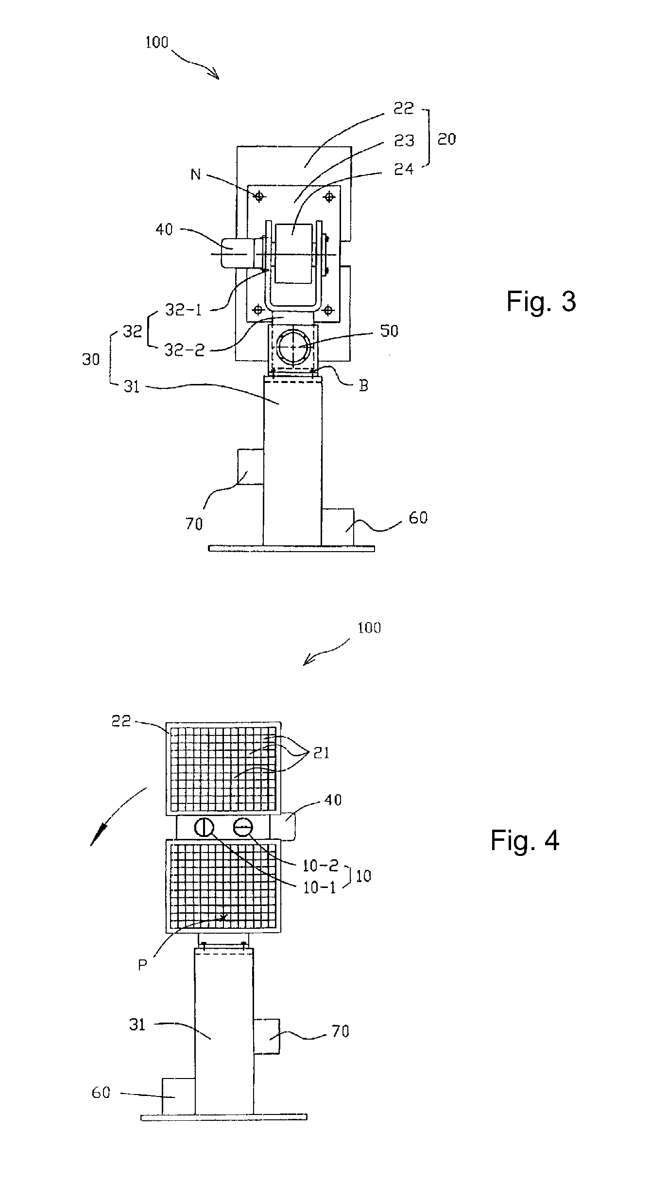
The present invention relates to a sun tracking sensor unit and a sun tracking apparatus having the same. There is provided a sun tracking apparatus, which comprises a sun tracking sensor unit 10 comprising an upright barrier 12 for partitioning a sensor case into four specific areas of east, west, south and north, CDS elements CDS(E), CDS(W), CDS(S), and CDS(N) respectively disposed in the four areas partitioned by the upright barrier 12, and the sensor case 11 functioning as a body for supporting the upright barrier and the CDS elements; a solar panel combination 20 including a solar panel 22 having a plurality of solar cells attached thereon and a solar support body 24 coupled to a rear thereof; a housing 30 functioning as a body for supporting the sun tracking sensor unit 10 and the solar panel combination 20; and an east-west driving motor 40 and a south-north driving motor 50, coupled to the housing to adjust an angle of the solar panel by rotating the solar support body respectively in east-west and south-north directions. Accordingly, its tracking accuracy is high due to the lower limit of trackable illumination intensity, and its whole structure is simple, thereby having a low manufacturing and maintenance cost.

Description

CROSS-REFERENCE TO RELATED PATENT APPLICATIONS[0001]This patent application is a continuation of co-pending PCT / KR2007 / 005354, filed Oct. 29, 2007, which claims the benefit of Korean Application No. 10-2007-0088774, filed Sep. 3, 2007, the entire teachings and disclosure of which are incorporated herein by reference thereto.DESCRIPTION[0002]1. Field of the Invention[0003]The present invention relates to a sun tracking sensor unit and a sun tracking apparatus having the same, and more particularly, to a sun tracking sensor unit, which has a high tracking accuracy since the lower limit of trackable illumination intensity is low and is simple in whole structure, and a sun tracking apparatus having the sun tracking sensor unit.[0004]Specifically, in the present invention, characteristics of a cadmium sulfide (CDS) photoconductive cell are used in sun tracking. That is, the characteristics of the CDS photoconductive cell include a characteristic in which its internal resistance is decrea...

Claims


Application Information

Patent Timeline
IPC IPC(8): F24J2/38F24J2/40F24J2/02F24S20/30F24S50/20
CPCF24J2/38F24J2/5424G01S3/781H02S20/00Y02E10/47Y02E10/50G01S3/7861H02S20/32F24S30/455F24S50/20H01L31/0475
Inventor YOON, JOO-PYOUNG
Owner YOON JOO PYOUNG
Learn More