
Electronic keyboard instrument

a keyboard instrument and keyboard technology, applied in the field of electronic keyboard instruments, can solve the problem of insufficient realization of ample acoustic sounds

Active Publication Date: 2010-08-05
YAMAHA CORP
View PDF15 Cites 16 Cited by
  • Summary
  • Abstract
  • Description
  • Claims
  • Application Information

AI Technical Summary

Benefits of technology

[0007]The present invention provides an electronic keyboard instrument that emits sounds in both upward and downward directions from speakers solely for upward sound emission and speakers solely for downward sound emission to thereby realize acoustics similar to that of acoustic piano, and constitutes rear parts of resonance chambers in a speaker box by a common partition plate to prevent the speaker box from being complicated in construction.
[0009]With this invention, acoustics similar to that of acoustic piano can be realized by emitting sounds in both upward and downward directions from the speakers solely for upward sound emission and the speakers solely for downward sound emission, and the speaker box can be prevented from being complicated in construction by constituting the rear parts of the resonance chambers by the common partition plate.
[0013]In that case, appropriate volumes can easily be allocated to the resonance chambers, thereby making it possible to efficiently dispose the speaker box at a position corresponding to a position where a grand piano soundboard is disposed.
[0015]In that case, the volumes of the resonance chambers can efficiently be ensured.
[0017]In that case, the space-saving inside the instrument main body can be achieved, while ensuring that the resonance chambers corresponding to the speakers for low pitch tones each have a large volume.

Problems solved by technology

However, the downward sound radiation in this keyboard instrument made by causing air vibration produced by the upwardly directed speakers to propagate downward via the open holes of the enclosure is insufficient in realizing ample acoustic sounds as provided by a grand piano.

Method used


Image

  • Electronic keyboard instrument
  • Electronic keyboard instrument
  • Electronic keyboard instrument

Examples


Embodiment Construction

[0031]The present invention will now be described in detail below with reference to the drawings showing a preferred embodiment thereof.

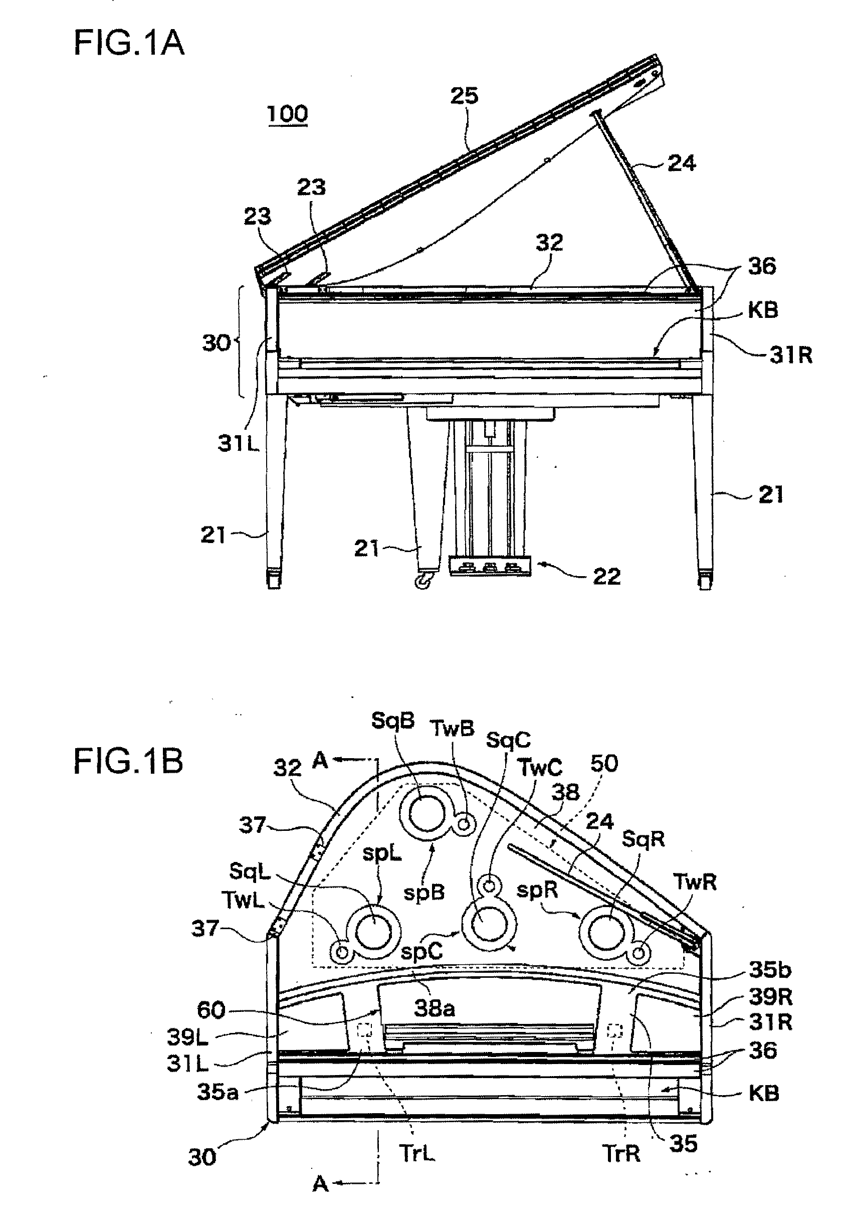
[0032]FIG. 1A shows in front view an electronic keyboard instrument according to one embodiment of this invention. The electronic keyboard instrument 100 is provided at an upper part thereof with an openable and closable roof plate 25, which is in an open state in FIG. 1A. FIG. 1B shows in plan view the keyboard instrument 100 in a state where the roof plate 25 is detached therefrom. In FIGS. 1A and 1B, a fallboard 36 that covers a keyboard KB is shown in an open state.

[0033]FIG. 2 shows the keyboard instrument 100 in bottom view, and FIG. 3 is a section view taken along line A-A in FIG. 1B. Illustrations of some constituent elements are omitted in FIG. 3.

[0034]As shown in FIGS. 1A and 2, the instrument main body 30 is supported by three legs 21. In the following, the terms “vertical direction”, “left-right direction” and “front-rear direction” refe...


PUM


Abstract

An electronic keyboard instrument that emits sounds in both upward and downward directions from speakers solely for upward sound emission and from speakers solely for downward sound emission to realize acoustics similar to that of acoustic piano, and constitutes rear parts of resonance chambers in a speaker box by a common partition plate to prevent the speaker box from becoming complicated in construction. Woofers directed downward are disposed at a lower part of the speaker box, and squawker directed upward are disposed at an upper part of the speaker box. The internal space of the speaker box is partitioned by one horizontal partition plate into an upper space where resonance chambers for the squawkers are defined by vertical partition plates and a lower space where resonance chambers for the woofers are defined by vertical partition plates. Rear parts of the resonance chambers are constituted by the horizontal partition plate.

Description

BACKGROUND OF THE INVENTION[0001]1. Field of the Invention[0002]The present invention relates to an electronic keyboard instrument having a speaker box.[0003]2. Description of the Related Art[0004]Conventionally, it has been known to provide an electronic keyboard instrument with a speaker box so as to ensure ample sound volume and produce musical tones with nuances close to those of acoustic piano (see, Japanese Patent Publication No. 3644356).[0005]In the keyboard instrument disclosed in this patent publication, speakers are mounted on an instrument main body so as to be directed upward and open holes are formed in and extend through an enclosure that covers rear surfaces of the speakers, whereby sounds are radiated upwardly and downwardly from the speakers and the open holes. Sounds radiated from the speakers are reflected by a reflector board of the keyboard instrument and transmitted to the audience, whereas sounds passing through the open holes are reflected by the floor and t...

Claims


Application Information

Patent Timeline
Patent Type & Authority Applications(United States)
IPC IPC(8): G10H1/32
CPCG10H1/32
Inventor KATO, TAKASHIFUJITA, TAKASHIISHIHARA, HIDEKISHINJO, AKIKOOBA, AKITO
Owner YAMAHA CORP
Learn More