
Release auto-grip locking tool

a technology of auto-grip and release mechanism, which is applied in the direction of pliers, manufacturing tools, etc., can solve the problems of inconvenient use, undesirable pinch point hazards for users, and inability to self-adjust, so as to maximize the power of levered clamping through gear reduction, maximize single-handed use, and improve safety and ease of use.

Inactive Publication Date: 2010-08-05
KELLY ARA DON
View PDF2 Cites 3 Cited by
  • Summary
  • Abstract
  • Description
  • Claims
  • Application Information

AI Technical Summary

Benefits of technology

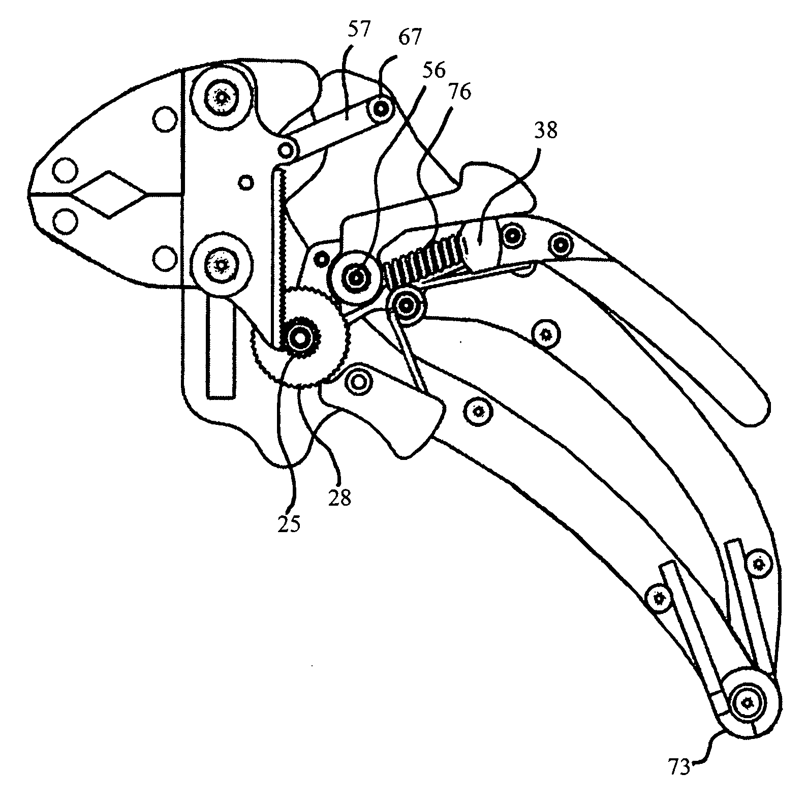
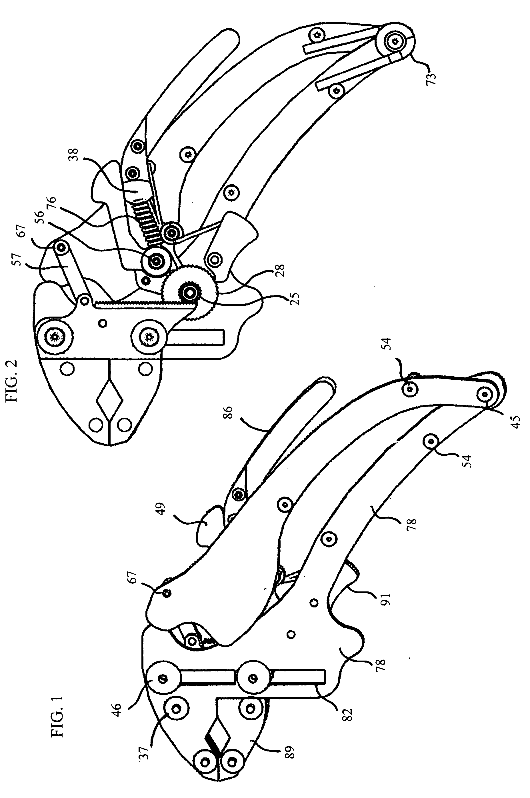
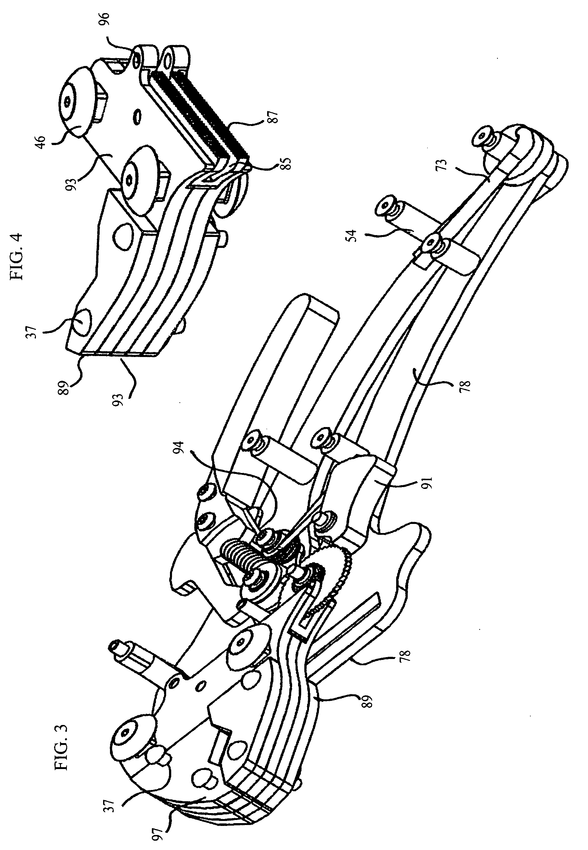
[0010]The present invention provides a release auto-grip locking tool that maximizes single handed ease of use thru leveraged clamping power to a workpiece that is located between its jaws to grip or lock the workpiece. In addition, parallel gripping surfaces maximize levered clamping power thru gear reduction substantially improving safety and ease of use.
[0012]As the jaws remain parallel, this tool design is particularly useful in applications for which spanners are used. The rear spring for the handles continually urge the jaws towards each other this allows a user the benefit of repositioning the tool without removing it from a bolt or other work piece.
[0014]Because the gripping surfaces move parallel to each other the tool can grip hex nuts or bolts using smooth gripping surfaces, in the manner of a “Crescent” wrench in addition with the release auto-grip locking tool you will not need to remove the tool from the work piece to reposition it.
[0017]In addition another benefit of the release auto-grip locking tool is a faster opening and closing speed of the jaws by way of the speed link, the speed link connects the upper handle and lower sliding jaw.

Problems solved by technology

In addition a condition which is not advantageous is the amount of pressure released to a users hand when the tool un-locked.
A pair of pliers for example, illustrated in U.S. Pat. No. 4,651,598 FIG. 1 shows a typical open rear handle configuration while grasping a work piece, that work piece could round off, crack or giveaway causing an undesirable pinch point hazard to the user.
Ordinary adjustable spanners do not have this pinch point, but they also do not self-adjust.
Prior to use on a workpiece the jaws must be adjusted manually to accommodate different size work pieces, this extra step makes conventional spanners less efficient compared to self-adjusting tools that could accomplish the same task.
The spanner also cannot lock or apply a levered force against a work piece, as a result the jaws could round off the corners of a bolt, slipping off causing an undesirable hazard to the user.

Method used


Image

  • Release auto-grip locking tool
  • Release auto-grip locking tool
  • Release auto-grip locking tool

Examples


Embodiment Construction

[0072]It is to be understood that the Figures and descriptions of the preferred embodiments of the present invention are to illustrate a clear understanding of the present invention, while for purposes of clarity, other elements because they do not facilitate a better understanding of the present invention were eliminated. Other elements may be advantageous in order to implement the present invention; one skilled in the art will recognize this. However, because such fundamentals are well known in the art, a discussion of such fundamentals is not provided herein.

[0073]In the present Detailed Description of the Invention, the preferred embodiments of the invention are illustrated as a release auto-grip locking tool of a distinct configuration. A person skilled in the art will recognize that the present invention may take on additional configurations and will be able to construct those configurations based upon the description presented herein.

[0074]It should be understood that other e...


PUM


Abstract

A release auto-grip locking tool designed for single hand use while maximizing safety and ease of use by way of isolating the release auto-grip feature from the leveraged power-gripping feature thus maximizing power to the jaws.The release auto-grip feature wherein the tool by design constantly applies a limited closing pressure to the jaws and where releasing the tool closes the tool jaws on any size work piece within the capability of said tool. The locking feature also works independently of the other features making possible a ratcheting locking feature that allows a user to increase locked gripping force to a work-piece without removing the tool.

Description

CROSS-REFERENCE TO RELATED APPLICATIONS[0001]As set forth in the Application Data Sheet, this utility application is a Continuation in Part of U.S. patent application Ser. No. 11 / 236,002 filed Sep. 26, 2005 now abandoned, and claims benefit of the subject matter in common with that application.STATEMENT REGARDING FEDERALLY SPONSORED RESEARCH OR DEVELOPMENT[0002]Not ApplicableREFERENCE TO SEQUENCE LISTING[0003]Not ApplicableBACKGROUND OF THE INVENTION[0004]Self-adjusting pliers are used to grip a workpiece with one hand, without the need to pre-adjust the pliers to accommodate the size of the workpiece.[0005]There have been a number of pliers that have jaws, one of which can be moved parallel to the other jaw and locked on a workpiece. Primarily these are toggle action pliers of a type that are exemplified by U.S. Pat. No. 358,746. With pliers of this toggle type, the jaws do stay parallel. In addition a condition which is not advantageous is the amount of pressure released to a user...

Claims


Application Information

Patent Timeline
IPC IPC(8): B25B7/12
CPCB25B7/10B25B7/123B25B7/12
Inventor KELLY, ARA DON
Owner KELLY ARA DON
Learn More