
Catalyst system, method of manufacture and use

a catalyst and catalyst technology, applied in the field of catalyst systems, methods of manufacture and use, can solve the problems of high cost of inorganic carriers used in the prior art, alter and complicate the synthesis of the catalyst of the present invention, etc. cost of the inorganic carriers of the prior art is much higher, and the thermomechanical and optical (transparency) properties of the final material are affected

Inactive Publication Date: 2010-07-29
CENT NAT DE LA RECHERCHE SCI
View PDF1 Cites 4 Cited by
  • Summary
  • Abstract
  • Description
  • Claims
  • Application Information

AI Technical Summary

Benefits of technology

[0046]In step (c) the introduction of the said solvent on the molecules of the polymer is done so that the polymer molecules organise in aggregates, micelles or vesicles. The concentration of polymer may be 0.1 mg / ml to 50 mg / ml. It may for example be 18 mg / ml in the case of polystyrenes carrying a benzoic acid function at the chain end and between 0.5 and 1 mg / ml in the case of block copolymers. The introduction of solvent can be carried out by the simple addition of the said solvent on the polymer molecules or on a mixture of polymer molecules and organic molecules.
[0062]In addition, the polyolefins synthesised using the catalytic system of the present invention have physical and chemical characteristics improved compared with those of the prior art. The catalyst and the catalyst activator penetrate inside the micelle and remain confined therein. This micelle fulfils the role of a nanoreactor within which the polymerisation reaction takes place.

Problems solved by technology

With regard to metallocenes, the cost of the co-catalyst is one of the major brakes on a greater economic development of these catalysts.
Thus one of the main limitations of these techniques of the prior art concerns the presence of residues of carriers in the synthesised polymer material, which may alter the thermomechanical and optical (transparency) properties of the final material.
Another limitation is the high cost of the inorganic carriers used in the prior art.
Finally, a third limitation is that the carriers used in the prior art do not make it possible to support all the catalytic systems developed, which greatly limits the use of the latter.
For a few years, manufacturers have been studying the use of “softer” organic carriers as substitutes for inorganic carriers, but no convincing result has been achieved.

Method used


Image

  • Catalyst system, method of manufacture and use
  • Catalyst system, method of manufacture and use
  • Catalyst system, method of manufacture and use

Examples


example 1

Synthesis of Copolymers

[0072]Linear polystyrenes carrying a benzoic acid (BA) function at the end of the chain as well as linear poly(styrene-b4-vinyl benzoic acid) (poly(St-b-BA) diblock copolymers are synthesised by Atom Transfer Radical Polymerisation (ATRP).

[0073]The polystyrenes carrying a terminal benzoic acid function are obtained by en mass polymerisation of the styrene using a 4-(1-bromo ethyl)benzoic acid initiator, as indicated in diagram 2 below.

[0074]The block copolymers are synthesised by en mass sequenced polymerisation of styrene and 4-vinyl methyl benzoate. The transformation of the ester function into a benzoic acid function is achieved in a second step by saponifiction reaction. The process of synthesis of the block copolymers (poly(St-b-BA) is summarised in diagram 3 below:

[0075]The characteristics of the copolymers are set out in table 1 below:

TABLE 1Characteristics of the linear polystyrenes carryinga benzoic acid function and poly(styrene-b 4-vinyl benzoicacid...

example 2

Putting Copolymers in Solution: Micellisation

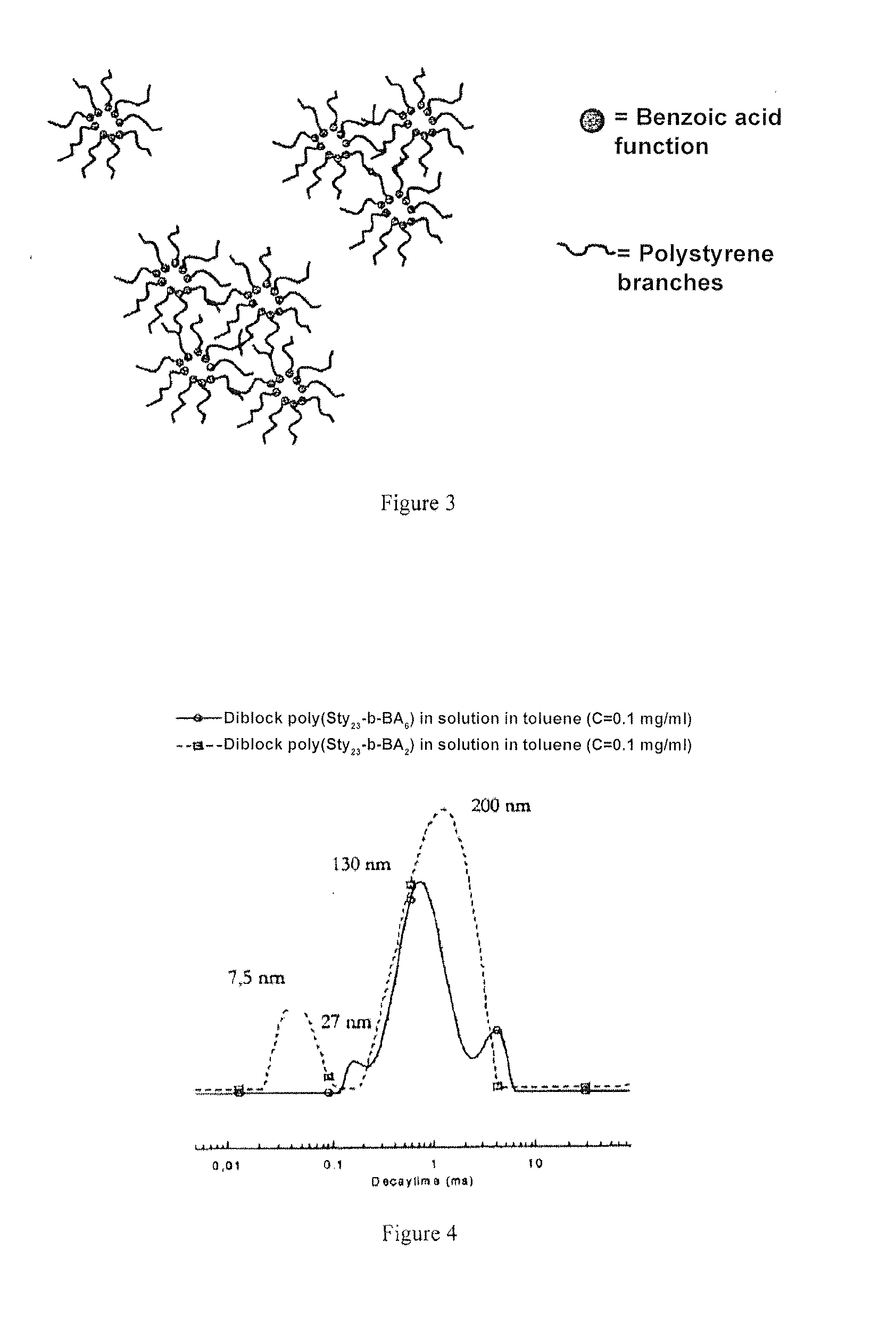
[0076]In solution in toluene, the linear polystyrenes manufactured in example 1 carry one or more benzoic acid functions organised to form micellar objects and micelle aggregates, with a size of approximately 200 nm. This behaviour is explained by the fact that toluene is a good solvent of polystyrene but not of 4-vinyl benzoic acid units, which self-assembly to form the core of the micellar objects.

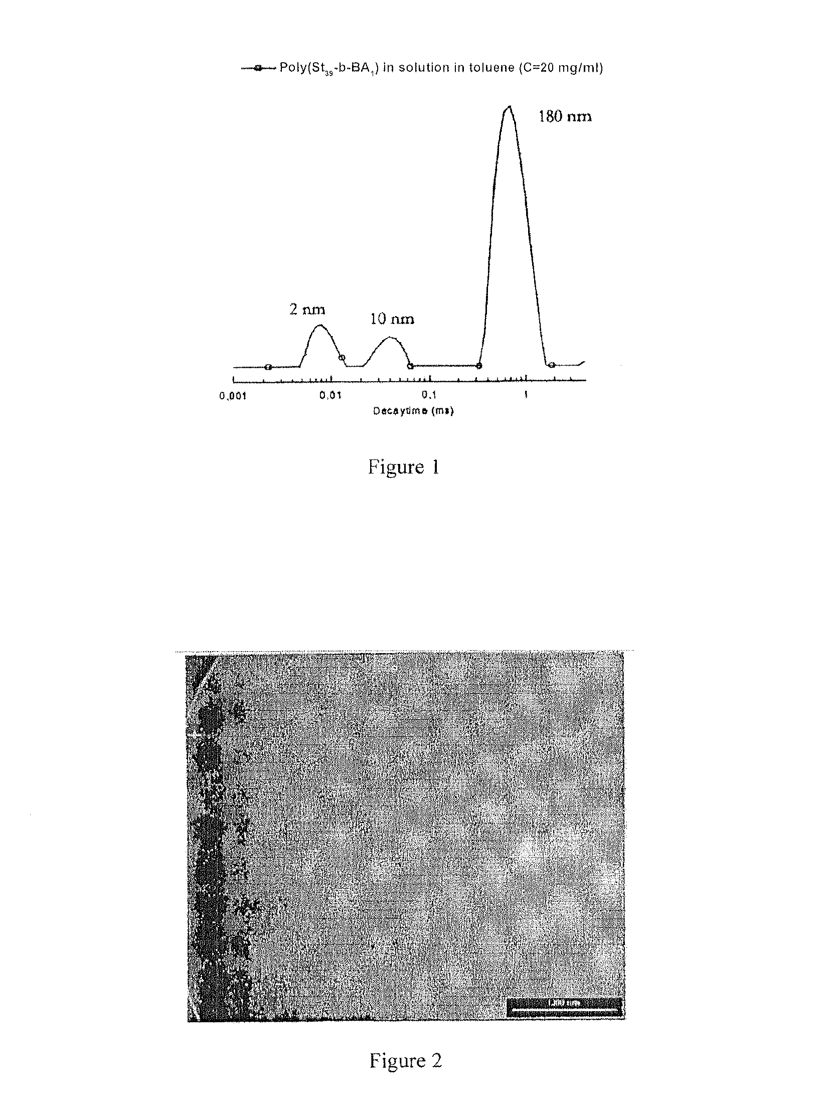
[0077]Associated auto system obtained from a polystyrene carrying a benzoic acid terminal function, with a molar mass of 3600 g / mol, in toluene: the size and distribution of the objects formed in toluene, measured by diffusion of light, are presented in the accompanying FIG. 1.

[0078]These results were confirmed by transmission electron microscopy (TEM) as testified to by the photograph presented in the accompanying FIG. 2, which is a transmission electron microscopy (TEM) image of the micelles and aggregates and micelles of linear polystyrene ...

example 3

Synthesis of Methylaluminoxane (MAO) within the Micelles

[0082]For the purpose of synthesising MAO, which is an activator of metallocenes and post-metallocenes, within the micellar systems manufactured in the above example, TMA is then added to the medium.

[0083]The TMA diffuses inside the micelles and then reacts with the encapsulated benzoic acid (see benzoic acid / TMA reaction described above). After two days of reaction at 60° C., a new analysis of the solution by diffusion of light shows that the size of the aggregates before and after the addition of TMA remains of the same order of magnitude. This is explained by the reaction of the TMA at the core of the micelles in order to form the aluminic compound with a structure of the MAO type.

[0084]It should be noted that, if the TMA had remained at the periphery of the micelles, a substantial increase in the size of the micelles and aggregates would have had to be observed. The data obtained by light diffusion after the addition of fre...


PUM

PropertyMeasurementUnit
concentrationaaaaaaaaaa
molar ratioaaaaaaaaaa

Abstract

The present invention relates to a catalyst system, to a method of manufacturing this system, and also to uses of this system. The catalyst system of the invention is characterized in that it comprises molecules of a polymer having, at one of its ends or along the chain, one or more polar functional groups; a solvent, said solvent, due to the fact of said polar functional group of said polymer, provoking and maintaining, when said molecules of the polymer are introduced thereinto, an organization of said molecules of the polymer into aggregates, micelles or vesicles so that the polar functional groups of said polymer are located inside the aggregates, micelles or vesicles formed; and a catalyst activator and a catalyst trapped in said aggregates, micelles or vesicles of said polymer. The catalyst system of the present invention may be used, for example, for catalyzing a (co)polymerization of olefins.

Description

[0001]The present invention relates to a catalytic system, to a method of manufacturing this system, and to uses of this system.[0002]The catalytic system of the present invention can be used for example for catalysing a polymerisation of olefins.[0003]The main application of the present invention are therefore found in the industry of polyolefins, for example polyethylene and polypropylene.[0004]In the field of polyolefins, catalysis research is particularly active. By way of example, the expenditure on research on catalysts by the largest producers of polyolefins reached 1 billion dollars annually solely for metallocene catalysts, that is to say 75% of all the expenditure made over a year by these companies in the field of research on polyolefins. With regard to metallocenes, the cost of the co-catalyst is one of the major brakes on a greater economic development of these catalysts.[0005]In 2003, some of the largest producers of polyolefins initiated a movement for externalising r...

Claims


Application Information

Patent Timeline
Patent Type & Authority Applications(United States)
IPC IPC(8): B01J31/12B01J31/06C08F4/76C08F4/80C08F4/52C08F4/12C08F4/00
CPCB01J13/02B01J31/12B01J31/143B01J31/165C08F10/00C08F10/02C08F110/02C08F4/6028C08F4/027C08F4/7042
Inventor CRAMAIL, HENRIBOUILHAC, CECILECLOUTET, ERICTATON, DANIELDEFFIEUX, ALAIN
Owner CENT NAT DE LA RECHERCHE SCI
Learn More