
Natural Gas Liquefaction Process

a natural gas and liquefaction technology, applied in the field of natural gas liquefaction, can solve the problems of high cooling load

Active Publication Date: 2010-07-29
EXXONMOBIL UPSTREAM RES CO
View PDF52 Cites 93 Cited by
  • Summary
  • Abstract
  • Description
  • Claims
  • Application Information

AI Technical Summary

Benefits of technology

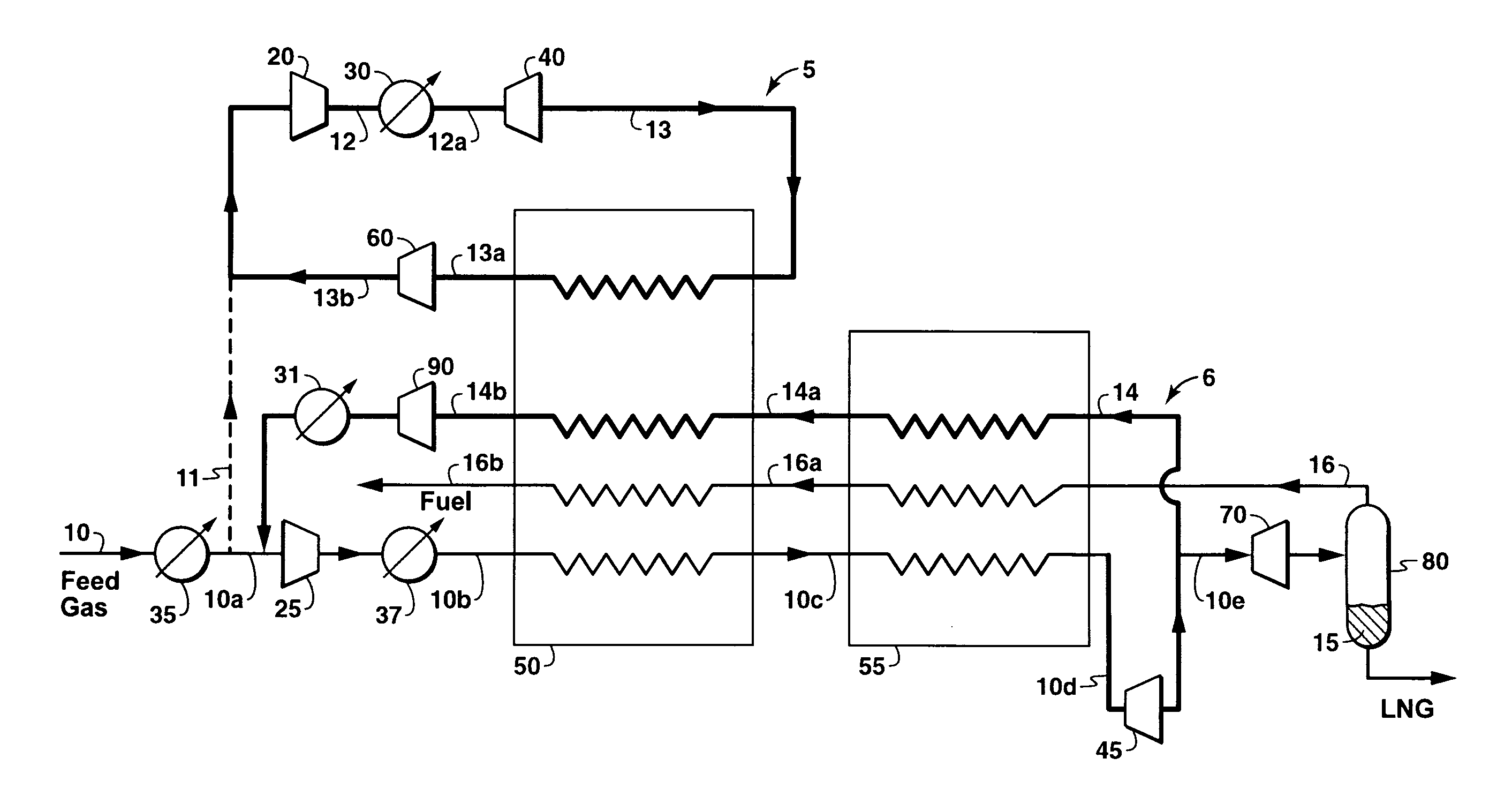
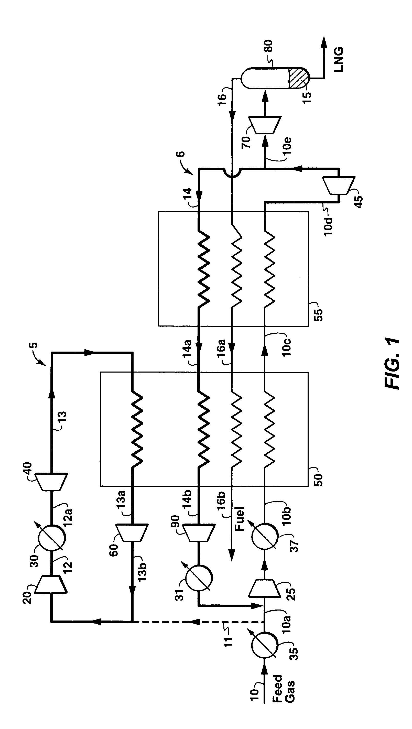
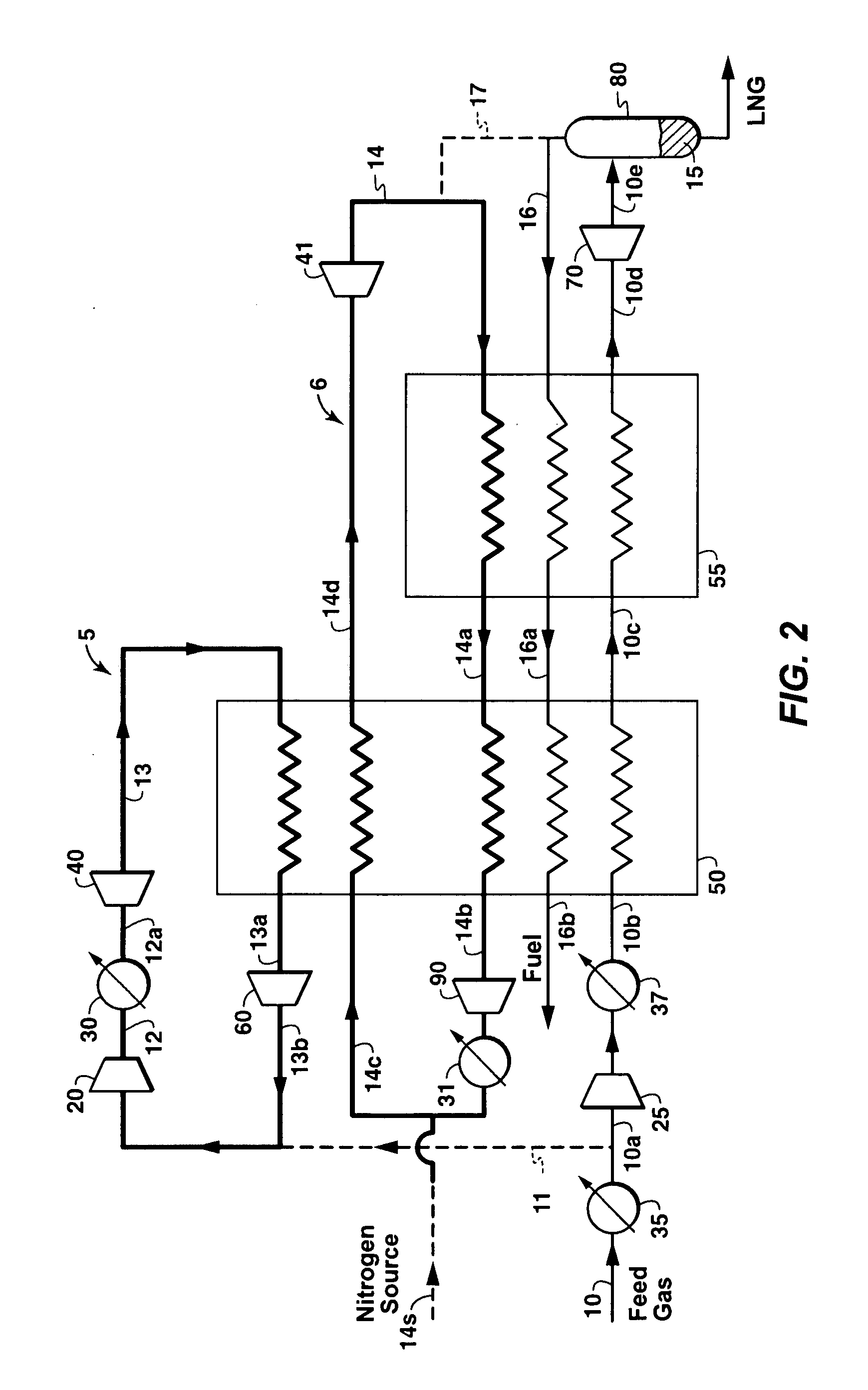
[0010]The invention is a process for liquefying a gas stream, particularly one rich in methane, said process comprising: (a) providing said gas stream at a pressure of from 600 to 1,000 psia as a feed gas stream; (b) providing a refrigerant at a pressure of less than 1,000 psia; (c) compressing said refrigerant to a pressure greater than or equal to 1,500-5,000 psia to provide a compressed refrigerant; (d) cooling said compressed refrigerant by indirect heat exchange with a cooling fluid; (e) expanding the refrigerant of (d) to cool said refrigerant, thereby producing an expanded, cooled refrigerant at a pressure of from greater than or equal to 200 psia to less than or equal to 1,000 psia; (f) passing said expanded, cooled refrigerant to a first heat exchange area; (g) compressing the gas stream of (a) to a pressure of from greater than or equal to 1,000 psia to less than or equal to 4,500 psia; (h) cooling said compressed gas stream by indirect heat exchange with an external cooling fluid; and, (i) passing said compressed gas stream through the first heat exchange area to cool at least a part thereof by indirect heat exchange, thereby forming a compressed, further cooled gas stream.

Problems solved by technology

Further, such refrigerants may have to be imported and stored imposing logistics requirements.
Because expander cycles result in a high recycle gas stream flow rate and resulting high cooling load, introducing inefficiencies for the primary cooling (warm) stage, gas expander processes such as described above further cool the feed gas after it has been pre-cooled using a refrigerant in a secondary cooling unit.

Method used


Image

  • Natural Gas Liquefaction Process
  • Natural Gas Liquefaction Process
  • Natural Gas Liquefaction Process

Examples


examples

[0030]The below presented tables and description depict performance curves and comparisons developed using an Aspen HYSYS® (version 2006) process simulator, a computer aided design program from Aspen Technology, Inc., of Cambridge Mass. The enthalpy values are calculated using the HYSYS process simulator. The enthalpy values are negative because of the enthalpy reference basis used by HYSYS. In HYSYS, this enthalpy reference basis is the heat of formation at 25° C. and 1 atm (ideal gas).

[0031]Table 1 illustrates the cooling load reduction for expander loop 5 and subcooling loop 6 when the cooling loads are compared from operating the feed gas at 1,000 psia (6895 kPa) versus 3,000 psia (20684 kPa), as discussed above.

[0032]Tables 2 and 3 below illustrate flow rate, pressures, and power consumption data using the invention process where the feed gas pressure at the entry to the primary heat exchange (e.g., 50) was varied from 1,000 psia (6895 kPa) to 5,000 psia (34474 kPa) while keepi...


PUM


Abstract

The described invention relates to processes and systems for treating a gas stream, particularly one rich in methane for forming liquefied natural gas (LNG), said process including: (a) providing a gas stream; (b) providing a refrigerant; (c) compressing said refrigerant to provide a compressed refrigerant; (d) cooling said compressed refrigerant by indirect heat exchange with a cooling fluid; (e) expanding the refrigerant of (d) to cool said refrigerant, thereby producing an expanded, cooled refrigerant; (f) passing said expanded, cooled refrigerant to a first heat exchange area; (g) compressing the gas stream of (a) to a pressure of from greater than or equal to 1,000 psia to less than or equal to 4,500 psia; (h) cooling said compressed gas stream by indirect heat exchange with an external cooling fluid; and heat exchanging the compressed gas stream with the expanded, cooled refrigerant stream.

Description

CROSS REFERENCE TO RELATED APPLICATIONS[0001]This application claims the benefit of U.S. Provisional Application No. 60 / 966,022, filed 24 Aug. 2007.TECHNICAL FIELD[0002]Embodiments of the invention relate generally to the liquefaction of gases, and more specifically liquefaction of natural gas, particularly the liquefaction of gases in remote locations.BACKGROUND[0003]Because of its clean burning qualities and convenience, natural gas has become widely used in recent years. Many sources of natural gas are located in remote areas, great distances from any commercial markets for the gas. Sometimes a pipeline is available for transporting produced natural gas to a commercial market. When pipeline transportation is not feasible, produced natural gas is often processed into liquefied natural gas (which is called “LNG”) for transport to market.[0004]In the design of an LNG plant, one of the most important considerations is the process for converting the natural gas feed stream into LNG. C...

Claims


Application Information

Patent Timeline
Patent Type & Authority Applications(United States)
IPC IPC(8): F25J1/00
CPCF25J1/0022F25J2270/08F25J1/0037F25J1/004F25J1/0042F25J1/0045F25J1/005F25J1/0072F25J1/0082F25J1/0092F25J1/0215F25J1/0219F25J1/025F25J1/0254F25J1/0288F25J2210/06F25J2220/62F25J2230/30F25J2270/02F25J2270/04F25J1/0035F25J1/0214
Inventor MINTA, MOSESSTONE, JOHN B.FEIST, RAYMOND SCOTT
Owner EXXONMOBIL UPSTREAM RES CO
Learn More