
Cover for a static roof vent

a roof vent and cover technology, applied in ventilation systems, lighting and heating apparatus, heating types, etc., can solve problems such as damage to the building structure, summary is not intended, etc., and achieve the effects of economics, durable use, and refined appearan

Inactive Publication Date: 2010-07-22
HASSENSTAB STEVE C
View PDF22 Cites 31 Cited by
  • Summary
  • Abstract
  • Description
  • Claims
  • Application Information

AI Technical Summary

Benefits of technology

[0010]The cover of this invention greatly reduces the possibility that wind-driven snow or rain may be driven downwardly through the throat portion of the static roof vent and into the attic of the building structure.
[0012]A further object of the invention is to provide a cover for a static roof vent which greatly reduces the possibility of wind-driven snow or rain being driven downwardly through the roof vent and into the attic over which the roof vent is positioned.
[0013]A further object of the invention is to provide a cover for a static roof vent wherein the cover may be easily secured to existing static roof vents.
[0014]A further object of the invention is to provide a cover for a static roof vent which is economical of manufacture, durable in use and refined in appearance.

Problems solved by technology

Moreover, this Summary is not intended for use as an aid in determining the scope of the claimed subject matter.
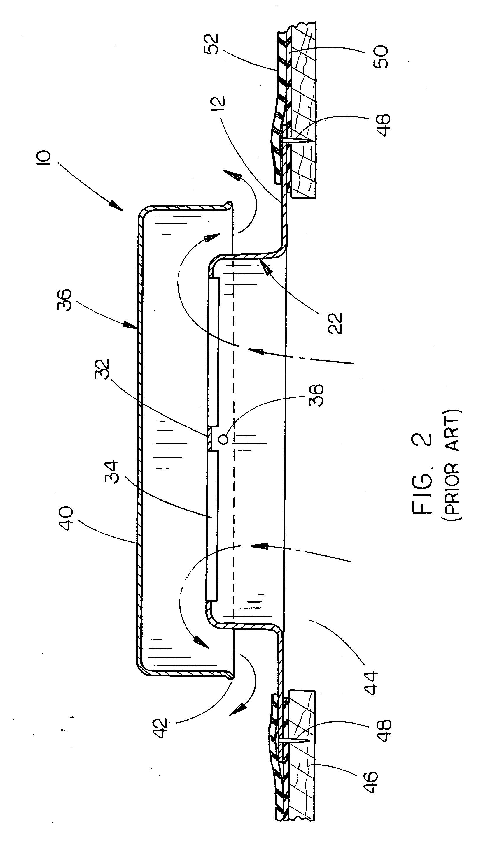
Although the conventional static roof vent described hereinabove performs satisfactorily to vent hot air from the building attic, wind-driven snow or rain may be blown beneath the lower end of the cap and into the louvers or vent openings formed in the upper end of the throat portion with the rain or show then passing downwardly through the vent opening in the building roof, which may cause damage to the building structure.

Method used


Image

  • Cover for a static roof vent
  • Cover for a static roof vent
  • Cover for a static roof vent

Examples


Embodiment Construction

[0023]Embodiments are described more fully below with reference to the accompanying figures, which form a part hereof and show, by way of illustration, specific exemplary embodiments. These embodiments are disclosed in sufficient detail to enable those skilled in the art to practice the invention. However, embodiments may be implemented in many different forms and should not be construed as being limited to the embodiments set forth herein. The following detailed description is, therefore, not to be taken in a limiting sense in that the scope of the present invention is defined only by the appended claims.

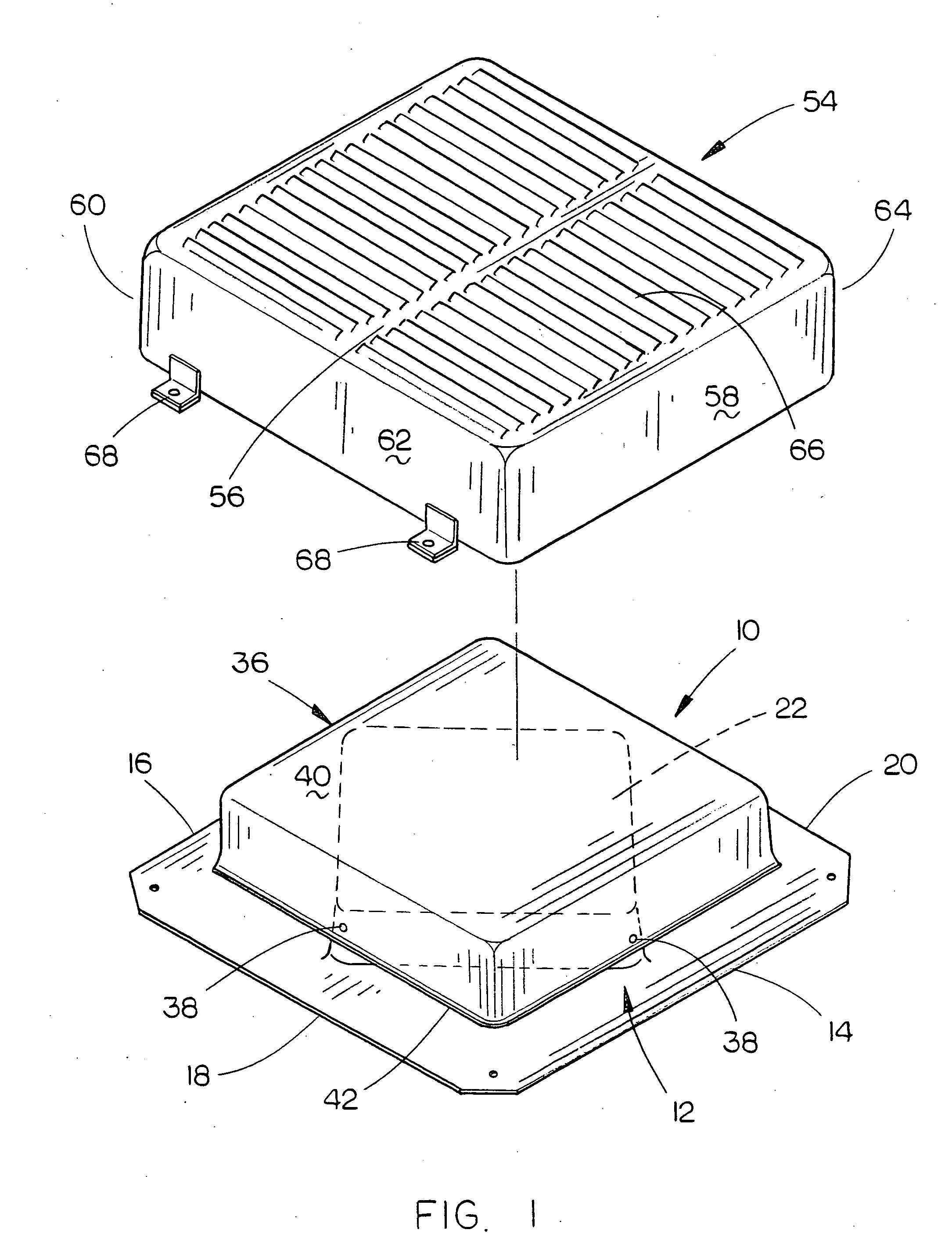
[0024]The numeral 10 refers to a prior art static roof vent which is of two-piece construction and is usually comprised of galvanized metal. Roof vent 10 includes a flat base member 12 having side edges 14, 16, 18 and 20. Integrally formed with base member 12 is a square or four-sided hollow throat portion 22 having upstanding side walls. 24, 26, 28 and 30. Roof vent 10 includes an...


PUM


Abstract

A cover is provided for a prior art static roof vent with the cover being positioned on the roof vent so as to permit the venting of attic air or the like from a building structure but which prevents wind-driven snow or rain from entering the interior of the roof vent.

Description

BACKGROUND OF THE INVENTION[0001]1 Field of the Invention[0002]This invention relates to a cover for a static roof vent and more particularly to a cover which is attached to a conventional static roof vent to prevent wind driven rain or snow from being blown downwardly through the static roof vent into the attic area therebelow.[0003]2. Description of the Related Art[0004]Static roof vents are utilized in conjunction with a vent opening formed in a building roof so that the hot air in the attic of the building may be vented outwardly through the vent opening and through the roof vent. The conventional static roof vents of the prior art do satisfactorily achieve venting of the attic but sometimes permit wind-driven rain and snow to be blown downwardly through the roof vent and through the vent opening into the attic which may cause damage to the building structure.SUMMARY OF THE INVENTION[0005]This Summary is provided to introduce a selection of concepts in a simplified form that are...

Claims


Application Information

Patent Timeline
IPC IPC(8): F24F13/20
CPCF24F7/02F24F13/20
Inventor HASSENSTAB, STEVE C.
Owner HASSENSTAB STEVE C
Learn More