Motor device mounted on mobile body and mobile body having the motor device mounted thereon
a technology of motor device and mobile body, which is applied in the direction of motor/generator/converter stopper, propulsion using engine-driven generators, propulsion parts, etc., can solve the problems of inverter-driven motors that may transiently have non-uniform voltage sharing, decrease in the vicinity of motors, and inability to resist electronic discharge in the air, etc., to inhibit motor insulation deterioration and excellent durability
- Summary
- Abstract
- Description
- Claims
- Application Information
AI Technical Summary
Benefits of technology
Problems solved by technology
Method used
Image

Examples
first embodiment
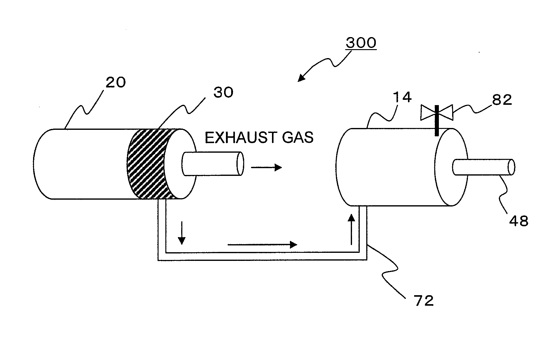
[0040]As shown in FIG. 4, in a motor device 300 mounted on a mobile body according to a first embodiment, a pressurizing mechanism for increasing the pressure in a motor chamber 14 in which a motor is installed has a compressor 30 which is driven to rotate by an engine 20 serving as driving means for driving the mobile body to produce compressed air for motor chamber pressurization, and the compressed air coming from the compressor 30 is fed into the motor chamber 14 through a pipe 72 almost constantly while the engine 20 is being driven.
[0041]The compressor 30, which may employ, for example, a turbocharger or a turbine, is driven using exhaust gas coming from the engine to produce compressed air. Therefore, because the compressor 30 is driven using exhaust coming from the engine 20, the energy consumption of the motor device 300 mounted on a mobile body can be reduced, and because the engine 20 already provided in the mobile body is used, the structure of the motor device 300 mount...
second embodiment
[0042]As shown in FIG. 5, in a motor device 310 mounted on a mobile body according to a second embodiment, a pressurizing mechanism for increasing the pressure in a motor chamber 14 in which a motor is installed has a compressor 32 which is driven to rotate by an output shaft 22 of an engine 20 serving as driving means for driving the mobile body, and the compressor 32 is integrated in the motor chamber 14, and produces compressed air for motor chamber pressurization to supply it directly into the motor chamber 14. Here, the compressed air coming from the compressor 32 is fed into the motor chamber 14 almost constantly while the engine 20 is being driven.
[0043]The compressor 32 may employ, for example, a turbocharger or a turbine, and because the compressor 32 is integrated in the motor chamber 14, the pipe 72 for feed as used in the first embodiment is unnecessary, which leads to a simpler structure and a lower cost. Further, because the compressor 32 is driven by the output shaft ...
third embodiment
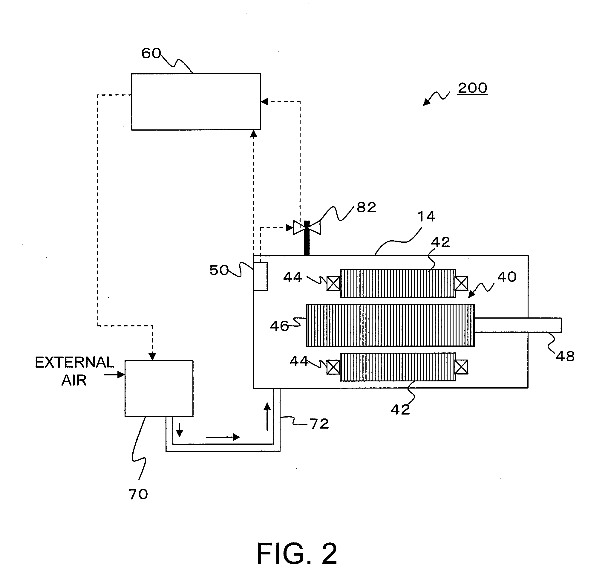
[0044]As shown in FIG. 6, in a motor device 320 mounted on a mobile body according to a third embodiment, a pressurizing mechanism for increasing the pressure in a motor chamber 14 in which a motor is installed has a compressor 34 which is driven by a dedicated motor 36 driven by power supply from a battery 38 to produce compressed air, and the compressed air coming from the compressor 34 is fed into the motor chamber 14 through a pipe 72. Here, the battery 38 may be controlled by the control unit 60 (FIG. 2) to supply power to the dedicated motor 36 in response to a drive signal from the control unit 60 in accordance with the internal pressure in the motor chamber 14.
[0045]In areas where the atmospheric pressure is low, such as at high elevations, the engine of a mobile body may become less efficient, and under such circumstances, for example, a hybrid vehicle may set the travel mode to a motor travel mode to suspend operation of the engine. During such suspension of operation of t...
PUM
 Abstract
Description
Claims
Application Information
 - R&D
- Intellectual Property
- Life Sciences
- Materials
- Tech Scout
- Unparalleled Data Quality
- Higher Quality Content
- 60% Fewer Hallucinations
Browse by: Latest US Patents, China's latest patents, Technical Efficacy Thesaurus, Application Domain, Technology Topic, Popular Technical Reports.
© 2025 PatSnap. All rights reserved.Legal|Privacy policy|Modern Slavery Act Transparency Statement|Sitemap|About US| Contact US: help@patsnap.com