
Aerial roof estimation system and method

a technology for estimating roofs and roofs, applied in the direction of mechanical measuring arrangements, instruments, and using mechanical means, can solve the problems of affecting the ability of roofing contractors, prohibiting time for travel and commuting, and removing the owner or key person on the current job site,

Active Publication Date: 2010-07-15
EAGLEVIEW TECH
View PDF45 Cites 63 Cited by
  • Summary
  • Abstract
  • Description
  • Claims
  • Application Information

AI Technical Summary

Benefits of technology

The patent describes a system and method for estimating the size, dimensions, and pitch angles of roof sections on a building using aerial images obtained from a roof estimating software program and an image file database. The system allows roof companies to input the physical address of the building and access the image file database to determine the geometry of the roof sections. The roof company can then use this information to prepare a report and estimate the overall shape, slopes, and square footage of the roof. The system can also be used by individuals or companies in other fields such as roofing, solar panel installation, and insurance. The technical effects of the system include improved efficiency in estimating the size and shape of roof sections, improved accuracy in estimating the cost of repair or replacement, and improved access to relevant information for special access or clean-up tasks.

Problems solved by technology

There are factors that impact the roofing contractor's ability to provide a timely written estimate.
If an estimate is needed suddenly at a distant location, the time for travel and the cost of commuting can be prohibitive.
If the roofing contractor is a small company, the removal of the owner or key person on a current job site can be time prohibitive.
Another factor that may impact the roofing contractor's ability to provide a written estimate is weather and traffic.
Unfortunately, not all roofs on a building are proper size, geometrical shape, or orientation for use with solar panels.

Method used


Image

  • Aerial roof estimation system and method
  • Aerial roof estimation system and method
  • Aerial roof estimation system and method

Examples


Embodiment Construction

)

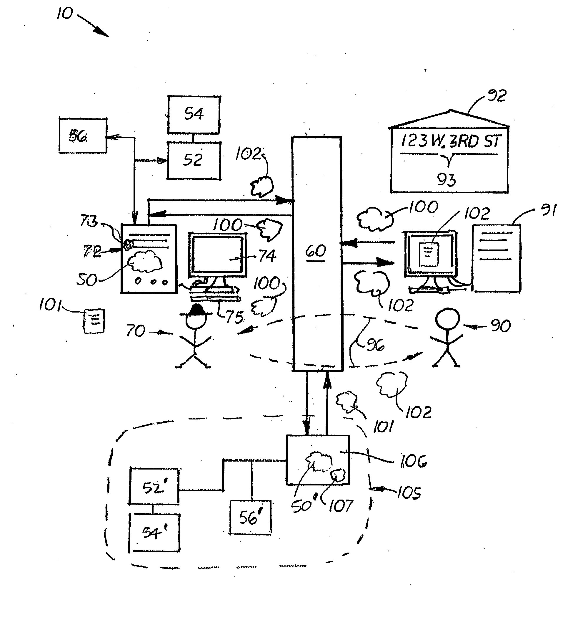
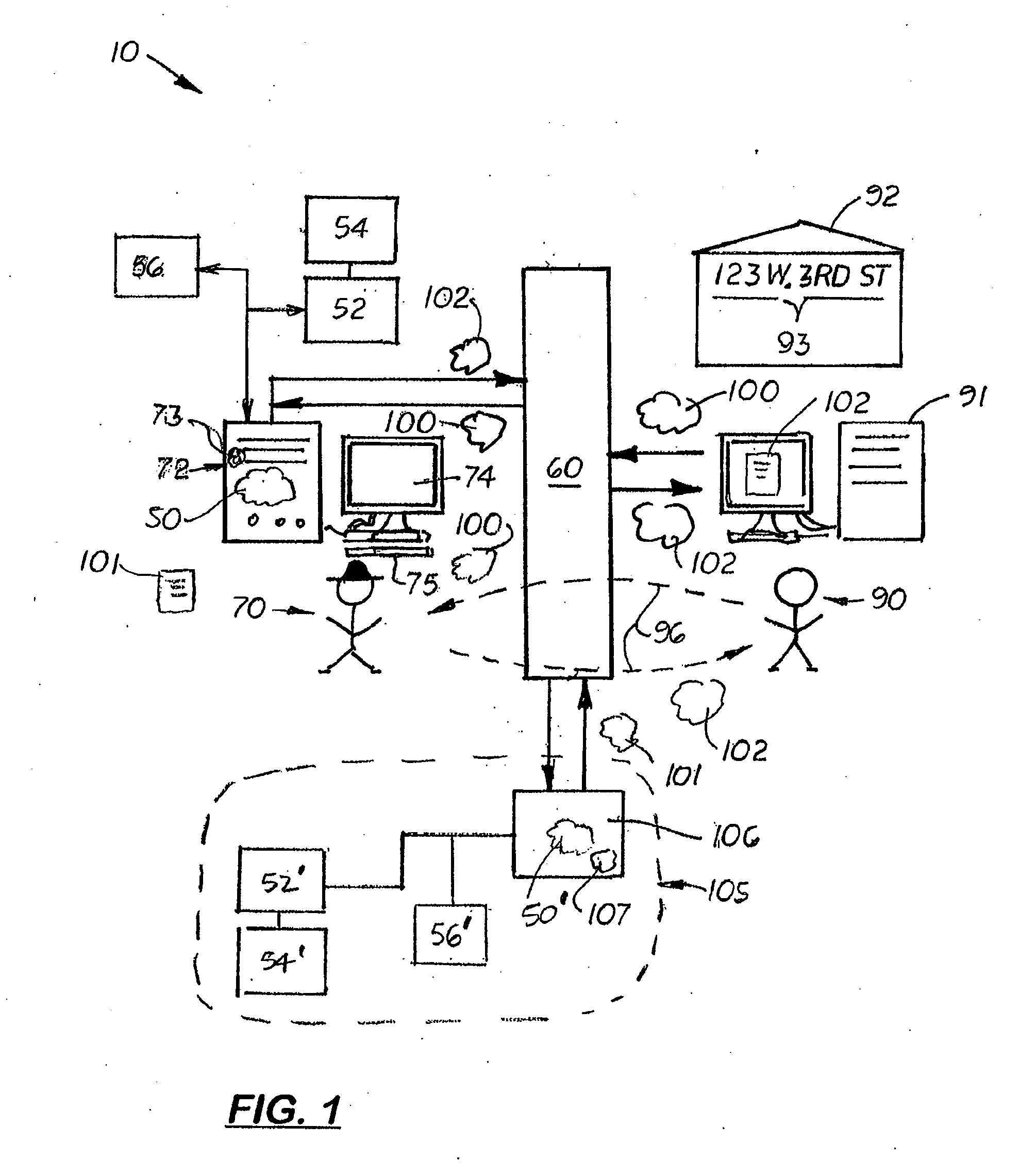
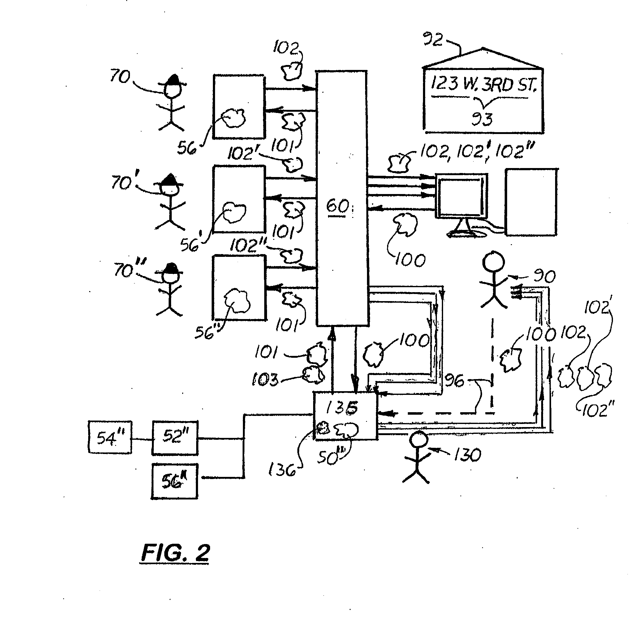
[0022] Referring to the accompanying Figs, there is described a system 10 and method that allows a roof company 70 to provide a final estimate 102 to a potential customer 90 to install equipment or to repair or replace the roof on a building 92 using aerial images of the building 92. The system 10 includes an estimating software program 50 designed to receive an address for the building 92. The software program 50 is linked to an aerial image file database 52 that contains aerial images files 54 of various building 92 in a region. The aerial image files 54 may be taken any available means, such as an aircraft, balloon, a satellite, etc. As shown in FIG. 3, the image files 54 typically include at least one a top plan view 65 and a perspective view 66 of the building 92. The image files 54 may also include a wide angle image file 67 showing the building 92 and the surrounding areas 93 around the building 92. In one embodiment, an image analysis and calibration module 52 is linked to ...


PUM


Abstract

A system that allows the remote measurement of the size, geometry, pitch and orientation of the roof sections of a building and then uses the information to provide an estimate to repair or replace the roof, or to install equipment thereon. The system includes an aerial image file database that shows aerial images of buildings in a designated area according to address. The slope and orientation images are typically oblique perspective views and top plan views of the buildings in the area. The system also includes an image analysis and calibration feature that enables the viewer to closely estimate the size, geometry and orientation of the building's roof sections. The information can then be used to prepare a cost estimate for the repair or replacement of the roof or installation of roof equipment. By simply inputting the potential customer's address, the company is able to determine the size, geometry, pitch and orientation of the roof sections of the building at that address, and then quickly provide an accurate estimate to the customer.

Description

[0001] This is a utility patent application which claims benefit of U.S. Provisional Application No. 60 / 925,072 filed on Apr. 17, 2007BACKGROUND OF THE INVENTION [0002] 1. Field of the Invention [0003] This invention relates to systems and methods for estimating construction projects, and more particularly, to such systems and methods that allow estimates involving roofs on buildings to be created remotely. [0004] 2. Description of the Related Art [0005] The information provided below is not admitted to be part of the present invention, but is provided solely to assist the understanding of the reader. [0006] Homeowners typically ask several roofing contractors to provide written estimates to repair or replace a roof on a house. Heretofore, the homeowners would make an appointment with each roofing contractor to visit the house to determine the style of roof, take measurements, and to inspect the area around the house for access and cleanup. Using this information, the roofing contra...

Claims


Application Information

Patent Timeline
Patent Type & Authority Applications(United States)
IPC IPC(8): G01B13/20
CPCG06Q10/00G06Q30/0283G06Q30/0206G06Q50/16G06Q40/08
Inventor PERSHING, CHRISCARLSON, DAVID
Owner EAGLEVIEW TECH
Learn More