
Base structure for a truck bed extension and ramp system

base structure technology, applied in the field of truck bed extensions, can solve the problems of not providing a standard mounting arrangement for retaining the truck bed extension in the box of any pickup truck, and it is difficult to manufacture a truck bed extension that has standard features

Inactive Publication Date: 2010-07-15
NODDIN MARTIN R +1
View PDF26 Cites 6 Cited by
  • Summary
  • Abstract
  • Description
  • Claims
  • Application Information

AI Technical Summary

Problems solved by technology

For this reason, it becomes difficult to manufacture a truck bed extension that has standard features for mounting to different makes of pickup trucks.
Although each of the prior art devices has its own merits, prior advances in this field has not provided a standard mounting arrangement for retaining a truck bed extension to the box of any pickup truck.

Method used


Image

  • Base structure for a truck bed extension and ramp system
  • Base structure for a truck bed extension and ramp system
  • Base structure for a truck bed extension and ramp system

Examples


Embodiment Construction

[0051]While this invention is susceptible of embodiment in many different forms, there are shown in the drawings and will be described in details herein, one specific embodiment of a base structure for a truck bed extension and ramp system. It should be understood that the present disclosure is to be considered as an example of the principles of the invention and is not intended to limit the invention to the embodiment illustrated and described.

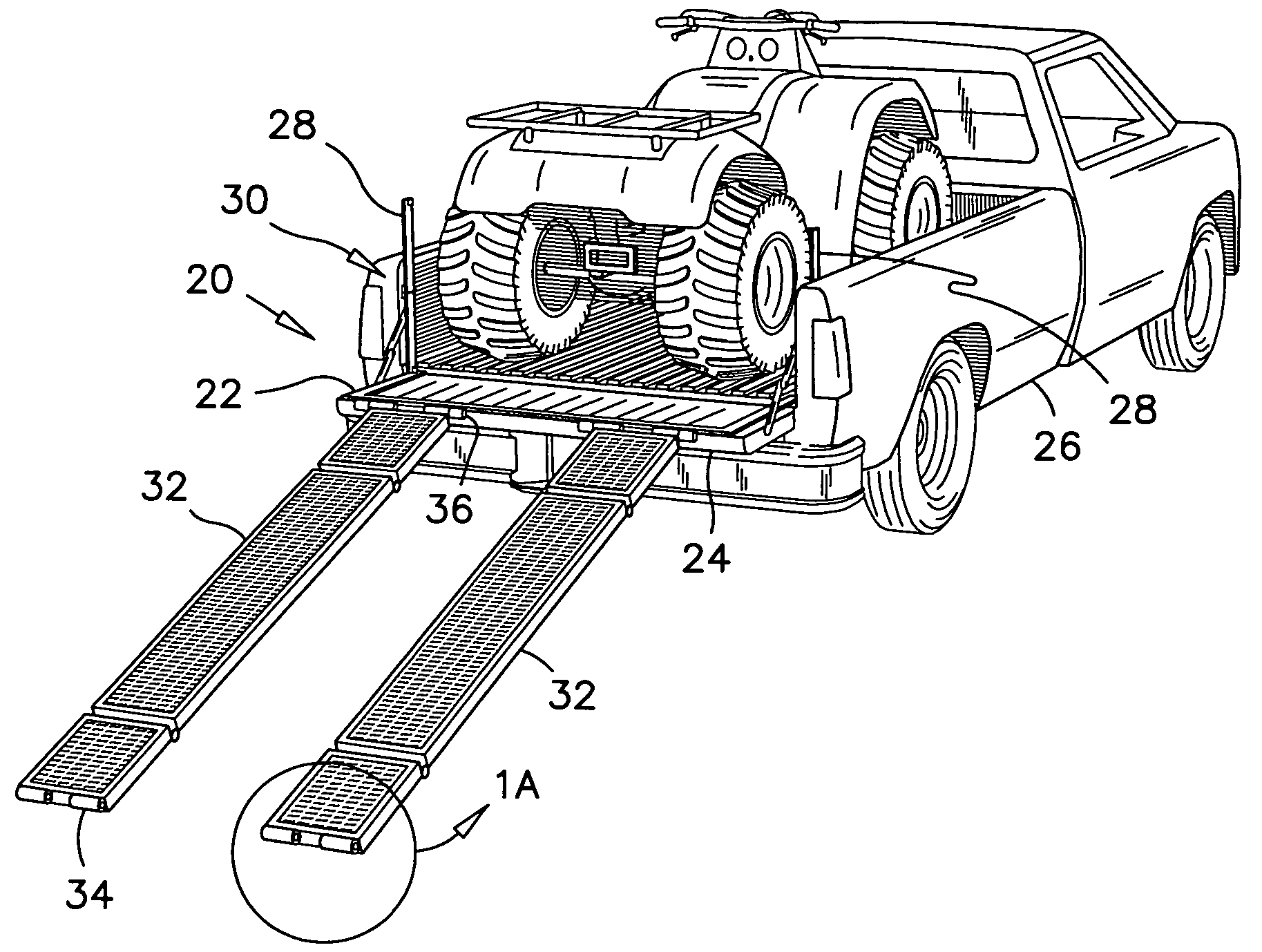
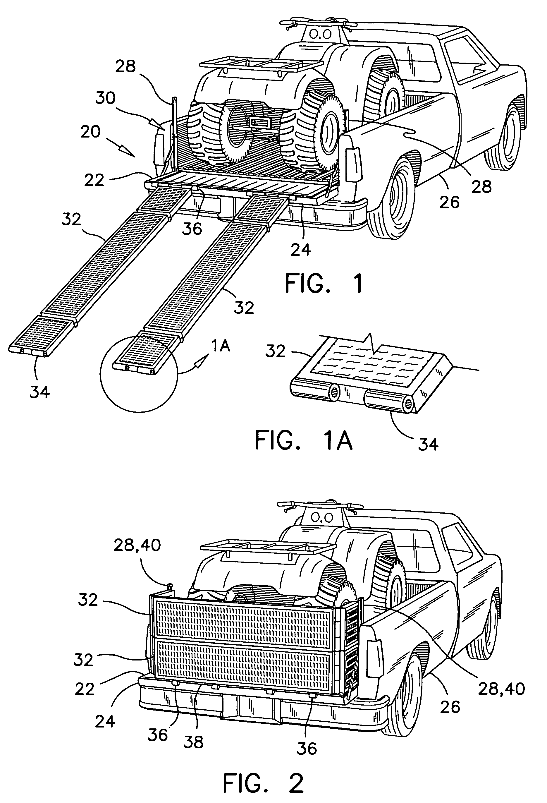
[0052]The preferred base structure 20 is illustrated with a pair of extended ramp members in use in FIG. 1, and with the ramp members in a stowed mode defining a truck bed extension in FIG. 2.

[0053]The base structure 20 has a horizontal U-shaped frame 22 which has a planar configuration and dimensions as to form a margin over the tailgate 24 of a pickup truck 26. A post 28 extends vertically at each end of the U-shaped frame 22. Each post 28 has a tailgate-latch coupler 30 movably mounted thereon for attachment to the tailgate latch member on...


PUM


Abstract

The base structure for a truck bed extension and ramp system has a horizontal U-shaped planar frame and dimensions for forming a margin over a tailgate of a pickup truck. A pair of posts extend vertically from the ends of the U-shaped frame. A tailgate-latch coupler is movably mounted on each post. This tailgate-latch coupler has dimensions for attachment to a tailgate latch member of a pickup truck. Each tailgate-latch coupler is movable up and down along the post and is connected to the tailgate latch member of a pickup truck and to retain the base structure to the truck box.

Description

FIELD OF THE INVENTION[0001]This invention pertains to truck bed extensions, and more particularly, this invention pertains to a base structure for retaining a truck bed extension and ramp system to the box of a pickup truck.BACKGROUND OF THE INVENTION[0002]The prior art contains numerous types of truck bed extensions. The following list provides a good sampling of the different designs available from the prior art.[0003]US D485,800 issued to D. P. Smith, on Jan. 27, 2004;[0004]U.S. Pat. No. 4,596,417 issued to K. D. Bennett, on Jun. 24, 1986;[0005]U.S. Pat. No. 5,820,188 issued to K. M. Nash, on Oct. 13, 1.998;[0006]U.S. Pat. No. 5,924,753 issued to D. R. DiBassie, on Jul. 20, 1999;[0007]U.S. Pat. No. 6,227,593 issued to R. K. De Valcourt, on May 8, 2001;[0008]U.S. Pat. No. 6,322,125 issued to C. E. Bauer, on Nov. 27, 2001;[0009]U.S. Pat. No. 6,340,190 issued to R. Rosebrugh et al., on Jan. 22, 2002;[0010]U.S. Pat. No. 6,378,926 issued to R. Renze et al., on Apr. 30, 2002;[0011]US ...

Claims


Application Information

Patent Timeline
Patent Type & Authority Applications(United States)
IPC IPC(8): B60P9/00B65G69/30
CPCB65G69/30B60P1/435
Inventor NODDIN, MARTIN R.NODDIN, ROBERT C.
Owner NODDIN MARTIN R
Learn More