
Delivery and recovery sheaths for medical devices

a technology for medical devices and sheaths, applied in the field of delivery and recovery sheaths, can solve the problems of buckling of the sheath, affecting the patient's health, and affecting the patient's life, and achieve the effect of enhancing frictional fit and preventing buckling

Inactive Publication Date: 2010-07-08
ABBOTT CARDIOVASCULAR
View PDF19 Cites 18 Cited by
  • Summary
  • Abstract
  • Description
  • Claims
  • Application Information

AI Technical Summary

Benefits of technology

[0012]The present invention provides delivery and recovery sheaths for use with expandable embolic filtering devices and other medical devices which deliver self-expanding components, such as self-expanding stents and vascular grafts, for implantation in a patient's vasculature. The present invention can be used with an embolic filtering device that generally includes a guide wire having a distal end, a self-expanding filter basket attached to the guide wire near its distal end, and a restraining sheath that maintains the self-expanding filter basket in a collapsed position until it is ready to be deployed in the patient. The present invention eliminates the need for a full-length restraining sheath which have been previously used to deploy and retrieve the filter basket. The present invention provides the physician with a rapid exchange delivery and recovery sheath which can eliminate the need to use long exchange wires when delivering or recovering the expandable filtering device and may reduce the time needed to perform the same. Moreover, the delivery sheath of the present invention can be used not only to deliver the filter to the target location in the patient's anatomy, but can also be used to collapse and retrieve the filtering device once the interventional procedure has been completed. As a result, the present invention eliminates the need for two separate sheaths to be supplied with a single filtering device since one sheath can perform both delivery and recovery functions.
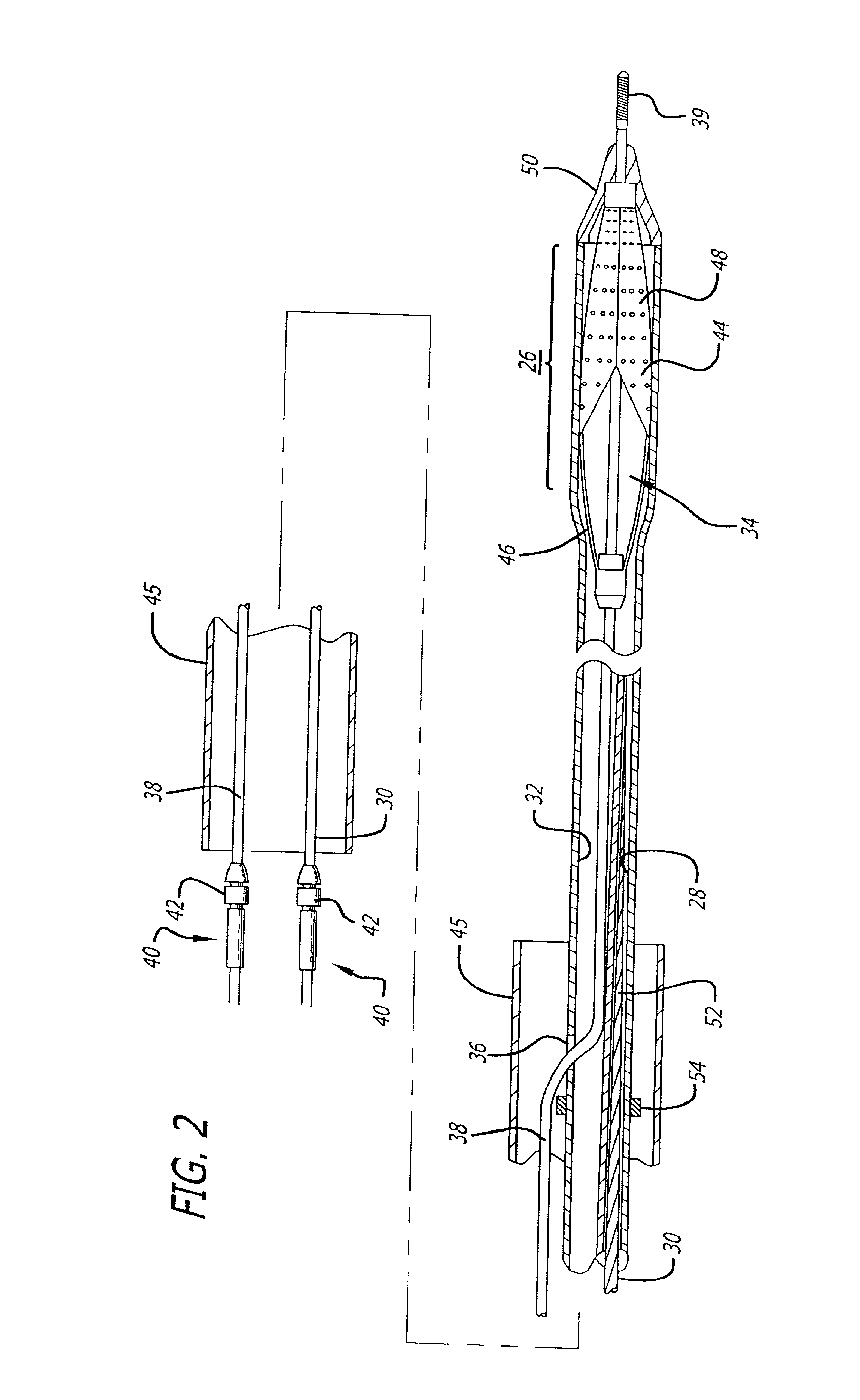
[0015]In another aspect of the present invention, the expandable housing portion of the sheath is stretchable and elastic to allow the sheath to hold the filter basket in place and prevent premature deployment. In this fashion, the housing portion of the sheath acts to “encapsulate” the filter basket, thus preventing it from being released from the sheath until the physician is ready to do so. Since the sheath is elastic and stretchable, it can achieve a number of different diameters and sizes when recovering or delivering the filtering device. For example, when the present invention is utilized as a recovery sheath, the housing portion will initially contract to its smaller diameter as it tracks along the guide wire of the embolic filtering device. As a result, the possibility that the tip of the sheath could scrape the walls of the body vessel causing a “snowplow” effect as the device is being advanced over the guide wire is reduced. After the distal tip of the housing portion starts to contact the filter basket, it will begin to expand radially to draw the basket into the housing portion. Once the distal tip starts to expand, the remainder of the sheath begins to expand somewhat allowing the filter basket to be drawn into the remainder of the housing portion. The housing portion has sufficient strength to impart an inward radial force that compresses the filter basket to its smaller diameter permitting the filter device to be subsequently removed from the patient. Once the basket is drawn into the housing portion of the sheath, it will be “encapsulated” to prevent emboli trapped in the filter basket from “back washing” into the body vessel, thus preventing the re-release of potentially damaging emboli into the patient's vasculature.
[0018]The present invention is also directed to a recovery sheath having an inner recovery tip which extends out of the distal tip of the recovery sheath and tracks along the guide wire of the embolic filtering device to prevent a “snowplowing” effect from occurring. The inner recovery tip and the outer recovery sheath are positioned such that a frictional fit between the inner recovery tip and outer recovery sheath is created to maintain the inner tip at the distal end of the recovery sheath as the two components are advanced simultaneously along the guide wire. The frictional fit can be enhanced by a frictional mechanism, such as overlapping ribs located on the surfaces of the recovery sheath and inner tip. Once the inner tip comes in contact with the proximal end of the filter basket and a sufficient amount of force is applied to the inner recovery tip, the frictional fit is overcome allowing the inner tip to slide back into the outer recovery sheath. The distal tip of the recovery sheath will now come in contact with the filter basket in order to collapse the basket. As the basket is retracted into the outer recovery sheath, the inner recovery tip continues to slide proximally back into the outer recovery sheath until the entire embolic filter device is completely recovered.

Problems solved by technology

However, there is one common problem associated with these procedures, namely, the potential release of embolic debris into the bloodstream that can occlude distal vasculature and cause significant health problems to the patient.
Angioplastic procedures which are performed in occluded saphenous vein grafts, implanted as a result of an open heart surgical procedure, pose a particularly difficult problem to the physician since a large amount of embolic debris is usually generated during the angioplasty procedure.
When any of the above-described procedures are performed in the carotid arteries, the release of emboli into the circulatory system can be extremely dangerous and sometimes fatal to the patient.
Debris that is carried by the bloodstream to distal vessels of the brain can cause these cerebral vessels to occlude, resulting in a stroke, and in some cases, death.
Therefore, although cerebral percutaneous transluminal angioplasty has been performed in the past, the number of procedures performed has been limited due to the justifiable fear of causing an embolic stroke should embolic debris enter the bloodstream and block vital downstream blood passages.
One technique which has had some limited success include the placement of a filter or trap downstream from the treatment site to capture embolic debris before it reaches the smaller blood vessels downstream.
While a filter can be effective in capturing embolic material, the filter still needs to be collapsed and removed from the vessel.
During this step, there is a possibility that trapped embolic debris can backflow through the inlet opening of the filter and enter the bloodstream as the filtering system is being collapsed and removed from the patient.
Often, when a restraining sheath is utilized, it can be difficult to properly turn the composite device to deliver the filter through the tortuous anatomy of the patient.
Moreover, during delivery, it is imperative that the restraining sheath remain positioned over the collapsed filter, otherwise the filter could be deployed prematurely in an undesired location in the patient's anatomy.
This occurrence can cause trauma to the walls of the patient's vasculature and would require the physician to re-sheath the expanded filter in order to further advance the filter into the desired area.
When a restraining sheath is utilized to deliver or recover an expandable filter in the patient's vasculature, the length of the sheath can sometimes be problematic to the physician as well.

Method used


Image

  • Delivery and recovery sheaths for medical devices
  • Delivery and recovery sheaths for medical devices
  • Delivery and recovery sheaths for medical devices

Examples


Embodiment Construction

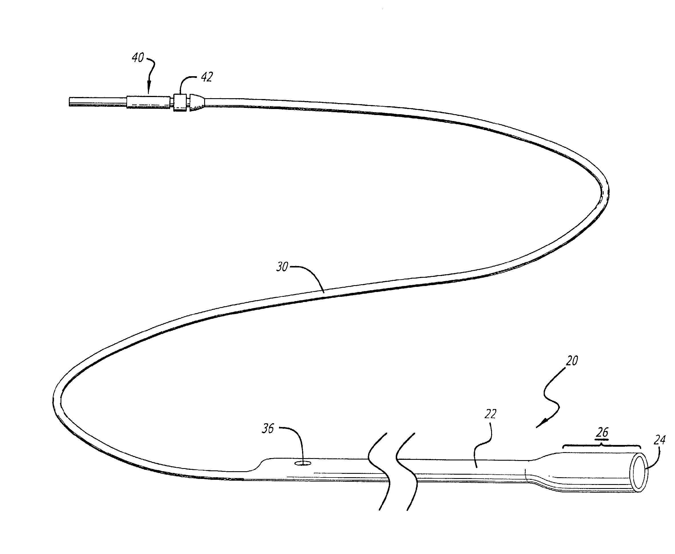
[0041]Turning now to the drawings, in which like reference numerals represent like or corresponding elements in the drawings, FIGS. 1 and 2 illustrate a restraining device 20 incorporating features of the present invention. This restraining device is adapted for use with a medical device, such as an expandable embolic filtering device designed to capture embolic debris which may be created and released into a body vessel during an interventional procedure. The restraining device 20 can be used both as a delivery sheath of placing the filtering device into the target area and a recovery sheath for retrieving the device from the patient.

[0042]FIGS. 1 and 2 show a particular embodiment of a restraining device 20 incorporating features of the present invention which includes a sheath 22 having a distal tip 24 and expandable housing portion 26. The sheath 22 is a tube-like member which has a lumen 28 extending proximally from the expandable housing portion 26 to receive the distal end of...


PUM


Abstract

A deployment control system provides controlled deployment of an embolic protection device which may include a guide wire, an expandable filter attached to the guide wire near its distal end, and a restraining sheath that maintains the expanded filter in a collapsed position. The deployment control system includes a torque control device which allows the physician to torque the guide wire into the patient's anatomy and a mechanism for preventing the guide wire from buckling as the restraining sheath is being retracted to deploy the expandable filter. A recovery control system for recovering the embolic protection device includes an inner catheter which extends within a lumen of an outer recovery sheath in a coaxial arrangement. A distal portion of the inner catheter extends beyond another recovery sheath during advancement of the recovery system into the vasculature. The recovery sheath can be advanced over the inner catheter to collapse the expandable filter. The proximal ends of the inner catheter and recovery sheath include handle portions having snap mechanisms which hold the components together as the recovery system is being advanced into the patient's vasculature.

Description

BACKGROUND OF THE INVENTION[0001]The present invention relates generally to delivery and recovery devices for use in conjunction with specialized medical devices, such as embolic filter used when an interventional procedure is being performed in a stenosed or occluded region of a body vessel to capture embolic material that may be created and released into the vessel during the procedure. The present invention also can be used to deliver other self-expanding medical devices, such as a self-expanding stent, within a patient's vasculature.[0002]Numerous procedures have been developed for treating occluded blood vessels to allow blood to flow without significant obstruction. Such procedures usually involve the percutaneous introduction of an interventional device into the lumen of the artery, usually through a catheter. One widely known and medically accepted procedure is balloon angioplasty in which an inflatable balloon is introduced within the stenosed region of the blood vessel to ...

Claims


Application Information

Patent Timeline
Patent Type & Authority Applications(United States)
IPC IPC(8): A61F2/84A61F2/01
CPCA61F2/013A61F2/95A61F2230/0006A61F2230/008A61F2002/018A61F2002/011A61F2/011
Inventor BOYLE, WILLIAM J.DENISON, ANDY E.HUTER, BENJAMIN C.HUTER, SCOTT J.PAPP, JOHN E.PETERSON, CHARLES R.STALKER, KENT C.B.
Owner ABBOTT CARDIOVASCULAR
Learn More