
Weather-resistant display

a display and weather-resistant technology, applied in static indicating devices, instruments, non-linear optics, etc., can solve the problems of damage to the display, many conventional displays, such as liquid crystal displays, are not weather-resistant, and are not suited to operate outsid

Inactive Publication Date: 2010-07-08
PANTEL JOSEPH +1
View PDF12 Cites 176 Cited by
  • Summary
  • Abstract
  • Description
  • Claims
  • Application Information

AI Technical Summary

Benefits of technology

The patent describes an outdoor weather-resistant display that can be used in various settings. The display includes a housing, a liquid crystal panel, a fan, a thermostat, a glass panel, and a circuit board. The housing has a cavity where the liquid crystal panel and fan are placed. The fan moves air from outside the housing to the cavity, across the liquid crystal panel, and out of the housing. The thermostat has a sensor in the cavity to monitor temperature. The glass panel covers the cavity and is sealed to the front housing. The circuit board is coated with a weather-resistant coating. The technical effects of this invention include improved durability and reliability of the display in various outdoor settings, as well as regulation of temperature within the display.

Problems solved by technology

Many conventional displays, such as liquid crystal displays, are not weather-resistant and therefore are not suited to operate outside in varying outdoor weather conditions, which includes various precipitation such as rain, snow, and hail; various temperature ranges such as in excess of 40° C. and below 0° C.; and various amounts of ambient light.
Exposing these displays to extreme temperature conditions, moisture, and other weather-related elements may damage the displays.
Other displays which are weather-resistant may have varying types of problems.
Some of these displays may not generate a bright enough image for viewing in direct sunlight.
Other displays may not be adapted to receive and transmit audio and video signals wirelessly.
Still other displays reflect too much ambient light, making it difficult for the user to view the viewing picture.
Further displays may suffer from additional types of problems.

Method used


Image

  • Weather-resistant display
  • Weather-resistant display
  • Weather-resistant display

Examples


Embodiment Construction

[0027]The following detailed description is of the best currently contemplated modes of carrying out the disclosure. The description is not to be taken in a limiting sense, but is made merely for the purpose of illustrating the general principles of the disclosure, since the scope of the disclosure is best defined by the appended claims.

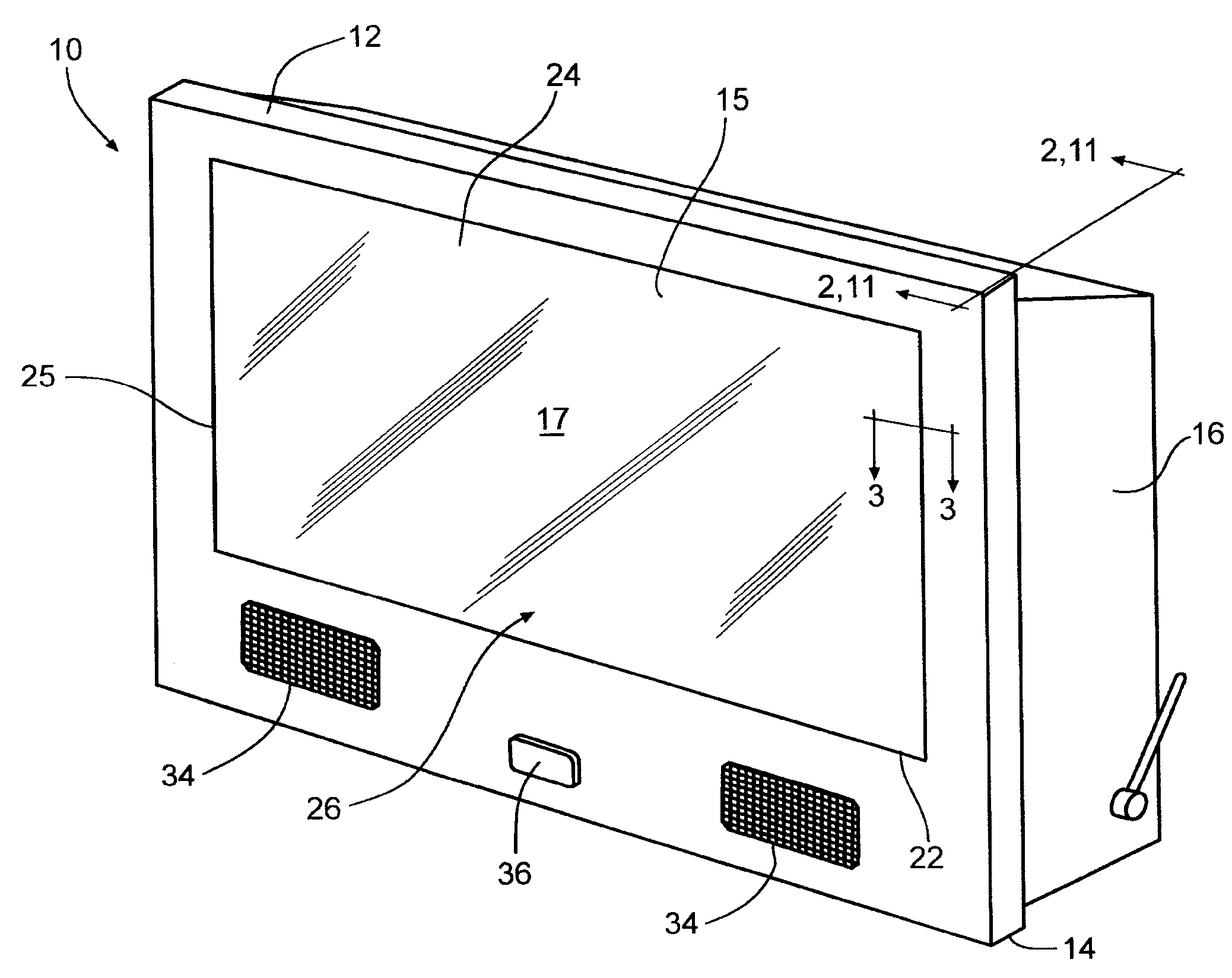
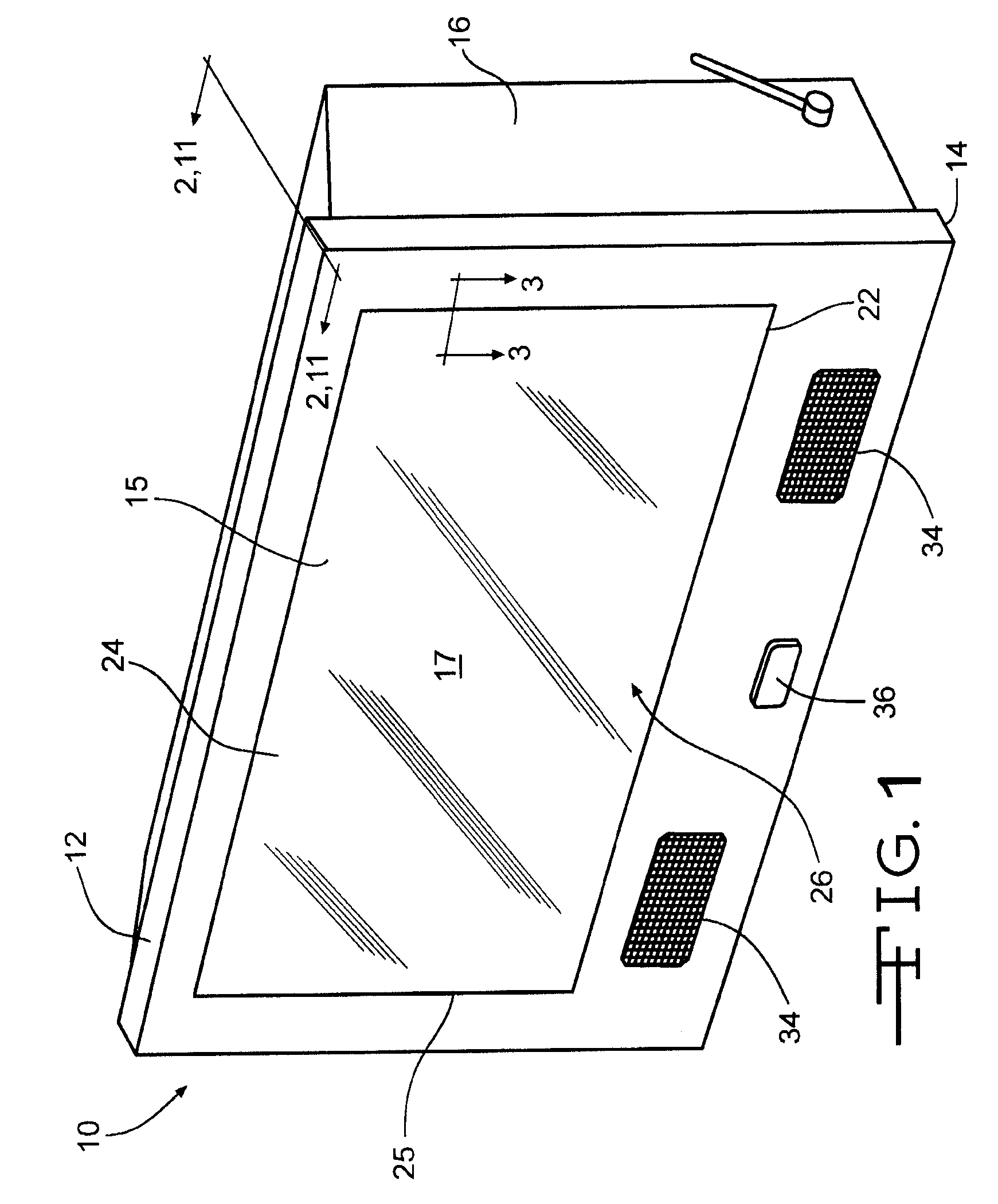
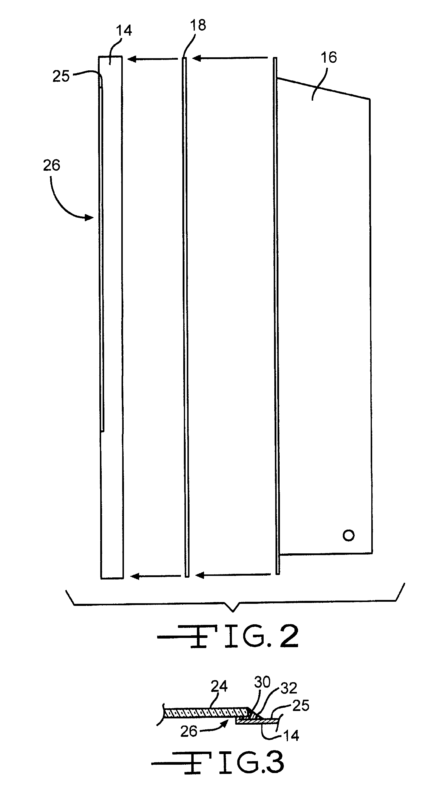
[0028]FIG. 1 is a right front perspective view of one embodiment of an outdoor weather-resistant display 10. The outdoor weather-resistant display 10 may comprise a liquid crystal display for viewing a picture and listening to audio. Preferably, the outdoor weather-resistant display 10 is resistant to outdoor weather conditions and includes components which aid in this effect. The outdoor weather-resistant display 10 may comprise a housing 12. The housing 12 may be made of a material having a high thermal conductivity in order to efficiently transfer heat from the display 10 to the atmosphere. Preferably, the housing 12 is made of a metal having a th...


PUM

PropertyMeasurementUnit
atmospheric temperatureaaaaaaaaaa
thicknessaaaaaaaaaa
angleaaaaaaaaaa

Abstract

An outdoor weather-resistant display may include a housing, an air-inlet, an air-outlet, a liquid crystal panel, a fan, and a thermostat. The air-inlet may be disposed through the housing into a cavity. The air-outlet may be disposed through the housing out of the cavity. The fan may be positioned to move air from outside the housing, through the air-inlet, into the cavity, across the liquid crystal panel, and out of the cavity through the air-outlet to outside the housing. The thermostat may have a temperature sensor within the cavity which provides temperature readings. The thermostat may control operation of the fan based on the temperature readings in order to regulate temperature within the cavity. The outdoor weather-resistant display may have further components to allow the display to operate in varying weather conditions, and to allow for wireless operation.

Description

FIELD OF THE DISCLOSURE[0001]The disclosure relates to displays, and more specifically, to weather-resistant displays for outdoor use.BACKGROUND OF THE DISCLOSURE[0002]Many conventional displays, such as liquid crystal displays, are not weather-resistant and therefore are not suited to operate outside in varying outdoor weather conditions, which includes various precipitation such as rain, snow, and hail; various temperature ranges such as in excess of 40° C. and below 0° C.; and various amounts of ambient light. Exposing these displays to extreme temperature conditions, moisture, and other weather-related elements may damage the displays. Other displays which are weather-resistant may have varying types of problems. Some of these displays may not generate a bright enough image for viewing in direct sunlight. Other displays may not be adapted to receive and transmit audio and video signals wirelessly. Additional displays may not be adapted to automatically change the brightness of t...

Claims


Application Information

Patent Timeline
Patent Type & Authority Applications(United States)
IPC IPC(8): G02F1/13G02F1/1333G02F1/133
CPCG02F1/133308G02F1/133385G02F2001/133311G02F2201/36G02F1/133311
Inventor PANTEL, JOSEPHCHI, LIAO CHUN
Owner PANTEL JOSEPH
Learn More