
Apparatus for fixing a wig and method for fixing a wig using the apparatus

a technology for fixing wigs and wigs, applied in the direction of applications, weaving, snap fasteners, etc., can solve the problems of user pain, wear or take off, wigs tend to slip out of place, etc., and achieve the effect of keeping the tangling state, increasing the states, and keeping the good wig wearing sta

Active Publication Date: 2010-07-08
ADERANS HLDG CO LTD
View PDF25 Cites 15 Cited by
  • Summary
  • Abstract
  • Description
  • Claims
  • Application Information

AI Technical Summary

Benefits of technology

[0020]In the apparatus according to the present invention, the monofilaments facing each other by folding the flexible plane sheet double to overlap the first half area with the second half area are entangled with, caught up in, and hardly pulled out from the parts of the user's natural hair pulled out from the first and second openings toward between the first half area and the second half area while holding the parts between the monofilaments. Namely, the apparatus according to the present invention produces the anchoring effect, thereby keeping the tangling state. Therefore, the user's natural hair pulled out between the first half area and the second half area can be firmly held. Besides, the first adhesive layer enters between the monofilaments and the user's natural hair thus entangled with and caught up in each other, and an adhesive force of the first adhesive layer produces the synergic effect of increasing the states in which they are entangled with and caught up in each other. The user's hair pulled out between the first half area and the second half area is firmly held and a good wig wearing state is kept. Further, since many monofilaments are protrusively provided, the surface of the first side of the flexible plane sheet is roughened, thereby reducing load required for release. Due to this, if the wig is to be detached from the user's head, an operation for detaching the apparatus is simplified. This can eliminate loss of the user's hair pulled out onto the flexible plane sheet and the pain in the user's head, and lessen the burden of the user.
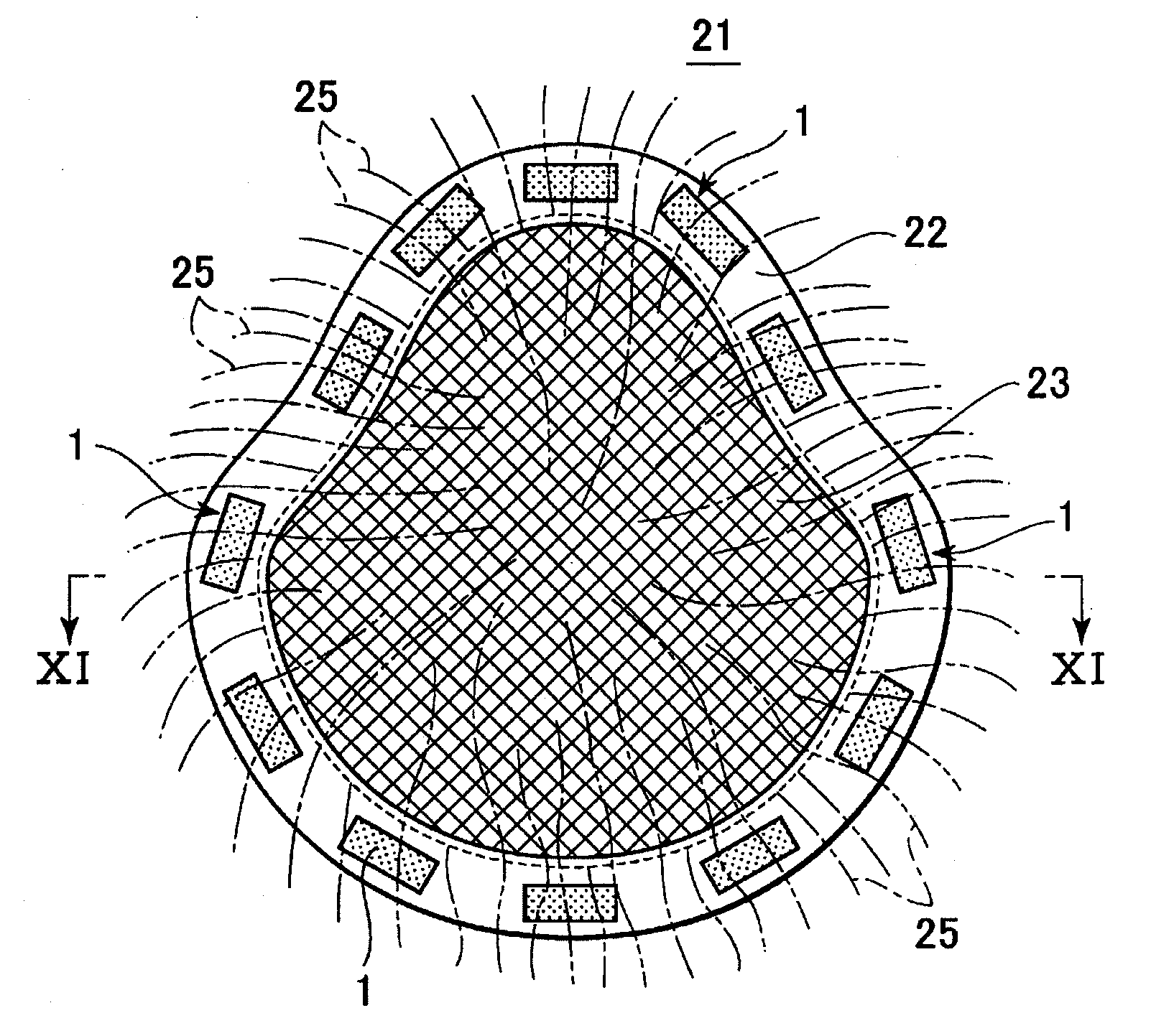
[0021]Furthermore, the first opening for pulling out the user's natural hair is provided at the position at which the apparatus is bent and the user's natural hair right under the first opening is pulled out. Due to this, the user's natural hair is not pulled strongly according to active movement of the user's head and the pain in the user's head can be lessened. Furthermore, the second opening is provided on the second half area of the apparatus and the user's natural hair is also pulled out from the second opening. By providing the second opening as well as the first opening, the wig is suppressed from floating or being turned up between the wig and the apparatus, and the user can wear the wig more stably. Besides, the wig can easily follow movement of the user's head, so that the pain in the head can be minimized even if the user's natural hair is pulled.BRIEF EXPLANATION OF DRAWINGS
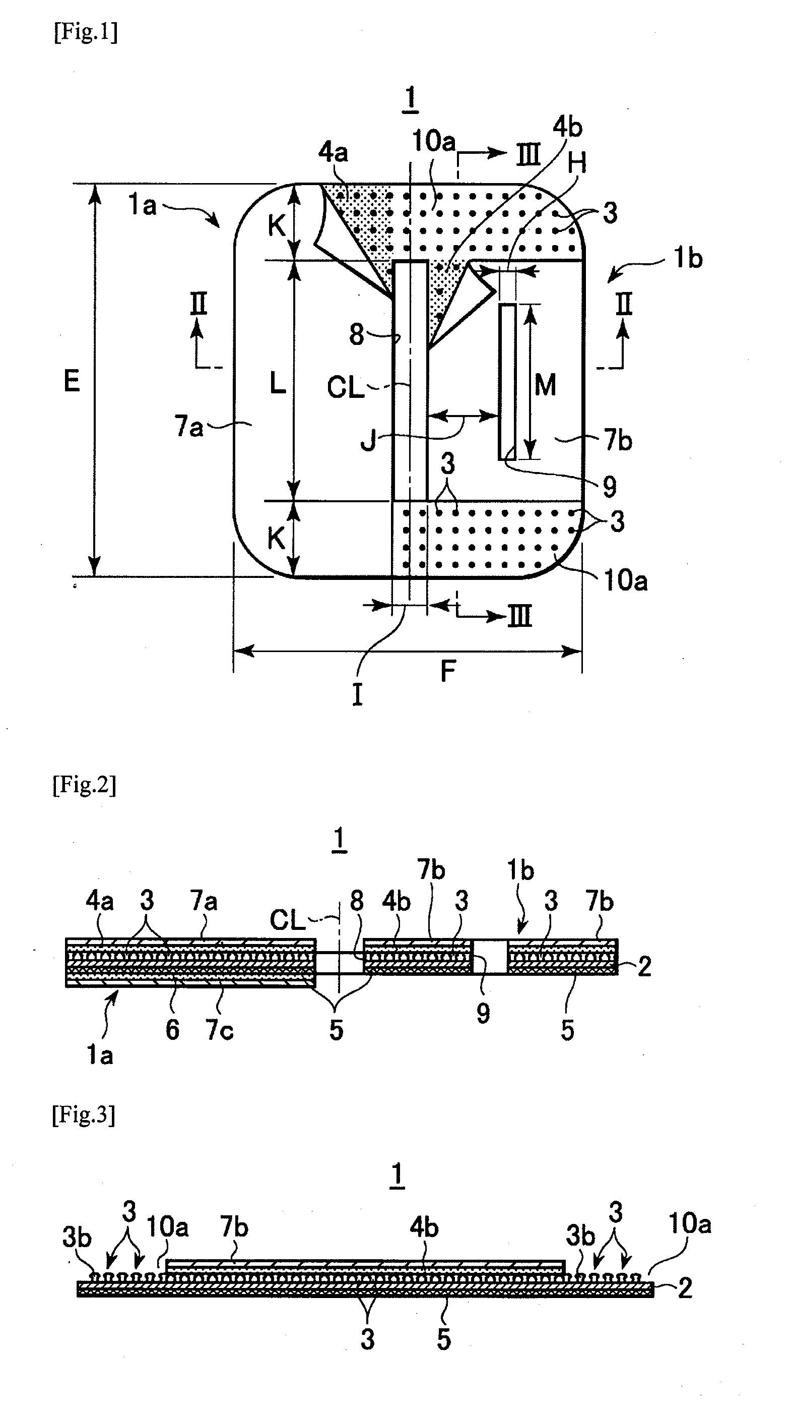
[0022]FIG. 1 is a plan view of an apparatus for fixing a wig according to an embodiment of the present invention;
[0023]FIG. 2 is a cross-sectional view taken along a line II-II of FIG. 1 according to the embodiment of the present invention;
[0024]FIG. 3 is a cross-sectional view taken along a line III-III of FIG. 1 according to the embodiment of the present invention;
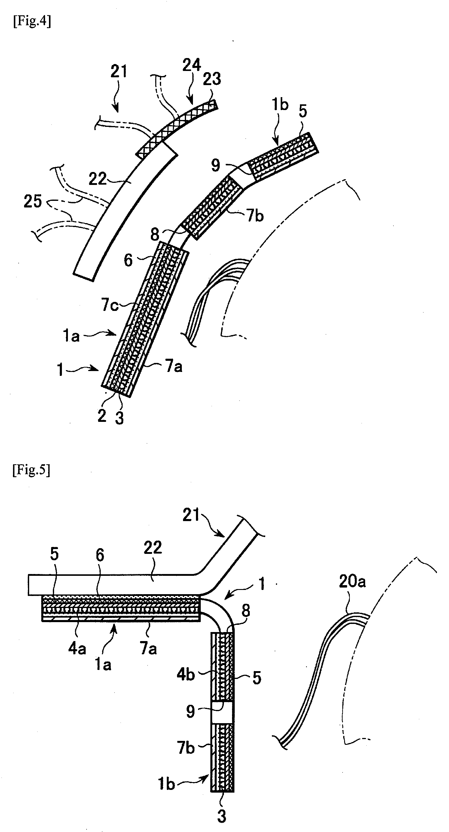
[0025]FIG. 4 is an explanatory view of procedures of attaching a wig to the user's head using the apparatus shown in the embodiment of the present invention;

Problems solved by technology

However, the method of pinching user's natural hairs by the clip having the pins arranged in a comb-teeth fashion as disclosed in Patent document 1 has the following problems.
Although the wig is easy to wear or take off, the wig tends to slip out of place because of a weak holding force.
Furthermore, while a user is asleep, the clip strikes against the user's head to make the user feel pain.
Due to this, it is inappropriate to use the wig for long time.
Moreover, the method of braiding user's natural hair into the base as disclosed in Patent document 2 has the following problems.
However, it takes long time to wear or take off the wig and to braid user's natural hair into the base, so that the user is restrained for long time.
However, the technique disclosed in Patent document 3 has the following problems.
Nevertheless, since user's natural hair is penetrated through the penetrating holes of the apparatus and fixed only by the adhesive layer that is made of a double-side tape, a force of fixing the user's natural hair is weak.
Moreover, since the adhesive layer that does not hold the user's natural hair has high adhesiveness, parts of the adhesive layer are bonded together when the apparatus is detached, making it difficult to take off the wig.
If the user puts forth out his or her strength, the wig is damaged or the scalp or hair of the user is possibly strained.
Furthermore, the technique disclosed in Patent document 4 has the following problems.
A fixing force of joining the male sheet and the female sheet of the surface fastener together is weak and the female sheet deteriorates faster than the male sheet.
Due to this, if the female sheet is joined with the male sheet, then the joined sheets become thick, the wig is floated while wearing the wig, and the user who wears the wig appears unnatural.

Method used


Image

  • Apparatus for fixing a wig and method for fixing a wig using the apparatus
  • Apparatus for fixing a wig and method for fixing a wig using the apparatus
  • Apparatus for fixing a wig and method for fixing a wig using the apparatus

Examples


example 1

[0082]The following conditions are set for the apparatus 1 employed in Example 1.[0083]Size of the flexible plane sheet 2: 25 mm in the length E, 20 mm in the width F, and 9 mm in the length G to the first opening 8 on the first half area 1a side[0084]Thickness of the flexible plane sheet 2: 0.15 mm[0085]Size of each monofilament 3: 0.25 mm in the diameter d1 of the stalk 3a, 0.40 mm in the height h1 of the stalk 3a, 0.40 mm in the diameter d2 of the head 3b, and 0.30 mm in the diameter d3 of the head 3b [0086]Interval between the heads 3b of the monofilaments 3: 0.30 mm in the interval c1 between the heads 3b and 0.15 mm in the interval c2 between the heads 3b [0087]Interval between the stalks 3a of the monofilaments 3: 0.40 mm in the interval c3 between the stalks 3a and 0.20 mm in the interval c4 between the stalks 3a [0088]Thickness of the first adhesive layers 4a, 4b: 0.10 mm.[0089]Adhesive force of the first adhesive layers 4a, 4b: 2.23 kg / cm.[0090]Thread diameter of the net m...

example 2

[0097]The apparatus 1 employed in Example 2 is the same as that in Example 1 except that the following conditions were set smaller than those in Example 1.[0098]Size of the flexible plane sheet 2: 20 mm in the length E[0099]Thickness of the flexible plane sheet 2: 0.11 mm[0100]Size of each monofilament 3: 0.20 mm in the diameter d1 of the stalk 3a, 0.21 mm in the height h1 of the stalk 3a, 0.22 mm in the diameter d2 of the head 3b, and 0.20 mm in the diameter d3 of the head 3b [0101]Interval between the heads of the monofilaments 3: 0.11 mm in the interval c1 between the heads 3b and 0.10 mm in the interval c2 between the heads 3b [0102]Interval between the stalks of the monofilaments 3: 0.22 mm in the interval c3 between the stalks 3a [0103]Thickness of the first adhesive layers 4a, 4b: 0.05 mm[0104]Adhesive force of the first adhesive layers 4a, 4b: 1.53 Kg / cm[0105]Thread diameter of the net member 5: 0.03 mm[0106]Number of meshes of the net member 5: 100 meshes / inch

example 3

[0107]The apparatus 1 employed in Example 3 is the same as that in Example 1 except that the following conditions were set larger than those in Example 1. It should be noted that only the height 1 of the stalk 3a is set smaller that that in Example 1 in view of the other conditions.[0108]Size of the flexible plane sheet 2: 30 mm in the length E and 28 mm in the width F[0109]Thickness of the flexible plane sheet 2: 0.20 mm[0110]Size of each monofilament 3: 0.40 mm in the diameter d1 of the stalk 3a, 0.38 mm in the height h1 of the stalk 3a, and 0.40 mm in the diameter d3 of the head 3b [0111]Interval between the heads 3b of the monofilaments 3: 0.30 mm in the interval c2 between the heads 3b [0112]Interval between the stalks of the monofilaments 3: 0.40 mm in the interval c4 between the stalks 3a [0113]Thickness of the first adhesive layers 4a, 4b: 0.20 mm[0114]Adhesive force of the first adhesive layers 4a, 4b: 3.00 kg / cm[0115]Thread diameter of the net member 5: 0.08 mm[0116]Number...


PUM

PropertyMeasurementUnit
heightaaaaaaaaaa
sizeaaaaaaaaaa
sizeaaaaaaaaaa

Abstract

An apparatus for fixing a wig to head of a user, including a flexible plane sheet including a first opening and a second opening, a plurality of monofilaments each including a swollen head and protrusively provided on a first side of the flexible plane sheet, a first adhesive layer provided so as to cover the monofilaments, a net member provided on a second side of the flexible plane sheet, and a second adhesive layer provided on the net member of a first half area, the flexible plane sheet being divided into the first half area and a second half area by a line bisecting the flexible plane sheet is provided. The first opening is provided on the line bisecting the flexible plane sheet while having a thin and long shape so that a part of natural hair of the user passes through the first opening, and the second opening is provided at a predetermined position on the second half area so that other part of the natural hair of the user passes through the second opening.

Description

TECHNICAL FIELD[0001]The present invention relates to an apparatus for fixing a wig having artificial hair transplanted to the head of a user and a method for fixing a wig using the apparatus.BACKGROUND ART[0002]There are known a wig stopper configured so that a clip having many pins arranged in a comb-teeth fashion is attached into an interior of a wig and so that the user's natural hairs are pinched between the pins (Patent document 1), and a wig attachment method including forming a base into which user's natural hairs are braided, putting the wig on the head, and sewing the base to a periphery of the wig (Patent document 2).[0003]However, the method of pinching user's natural hairs by the clip having the pins arranged in a comb-teeth fashion as disclosed in Patent document 1 has the following problems. Although the wig is easy to wear or take off, the wig tends to slip out of place because of a weak holding force. Furthermore, while a user is asleep, the clip strikes against the...

Claims


Application Information

Patent Timeline
Patent Type & Authority Applications(United States)
IPC IPC(8): A41G5/00
CPCA41G3/0008A41G3/0041Y10T442/2738Y10T442/172Y10T428/24017Y10T24/2708Y10T24/33A41G3/005A41G3/0091
Inventor TOBA, MAYUMI
Owner ADERANS HLDG CO LTD
Learn More