
Method and apparatus for monitoring power consumption

a technology for monitoring power consumption and power consumption, applied in the direction of transmission monitoring, instruments, analysing/displaying, etc., can solve the problems of reducing power loss, unintentionally, consumer may realize that a light or other appliance has been left on, or the freezer door has been left open, etc., to improve and improve power consumption monitoring. more timely awareness, the effect of quickly resolving low quality power or unavailability

Inactive Publication Date: 2010-07-01
POWERKUFF
View PDF16 Cites 72 Cited by
  • Summary
  • Abstract
  • Description
  • Claims
  • Application Information

AI Technical Summary

Benefits of technology

"The invention is a power consumption monitoring system that allows for improved and more accurate monitoring of power consumption and anomalies in power usage. The system includes magnetic cores that are placed around wires, cables, or conductors that transmit electric power. The system also includes wireless or reconfigurable sensors that can be easily integrated with existing infrastructure. The monitoring devices can display, communicate, or retransmit the power consumption information in real-time or historically. The system also allows for comparison of power usage to historical data and evaluation of costs. The software program can communicate the information to users or consumers through text, voice, fax, or email messages. Overall, the invention provides a more effective and efficient way to monitor and manage power consumption."

Problems solved by technology

In addition, the wrapping of a core around the current-carrying cable balances the unbalanced magnetic fields surrounding the cable, which unexpectedly reduces power loss.
For example, a consumer may realize that a light or other appliance has been left on, or a freezer door left open, unintentionally.
While the core and device disclosed and claimed in the prior art '218 and '872 Patents assist in accomplishing the goal of decreasing power consumption, they do suffer some deficiencies.
At most times, more than one electrically powered appliance is being used in the building; therefore, it can be difficult to pinpoint exactly which appliance is the most inefficient.
Also, while the prior art devices include a monitor with units calibrated to show the amount of power being consumed, the monitor displays only the present power consumption and cannot provide any information as to past usage, averages per different times of day, or other information that might be useful in profiling and reducing power consumption.

Method used


Image

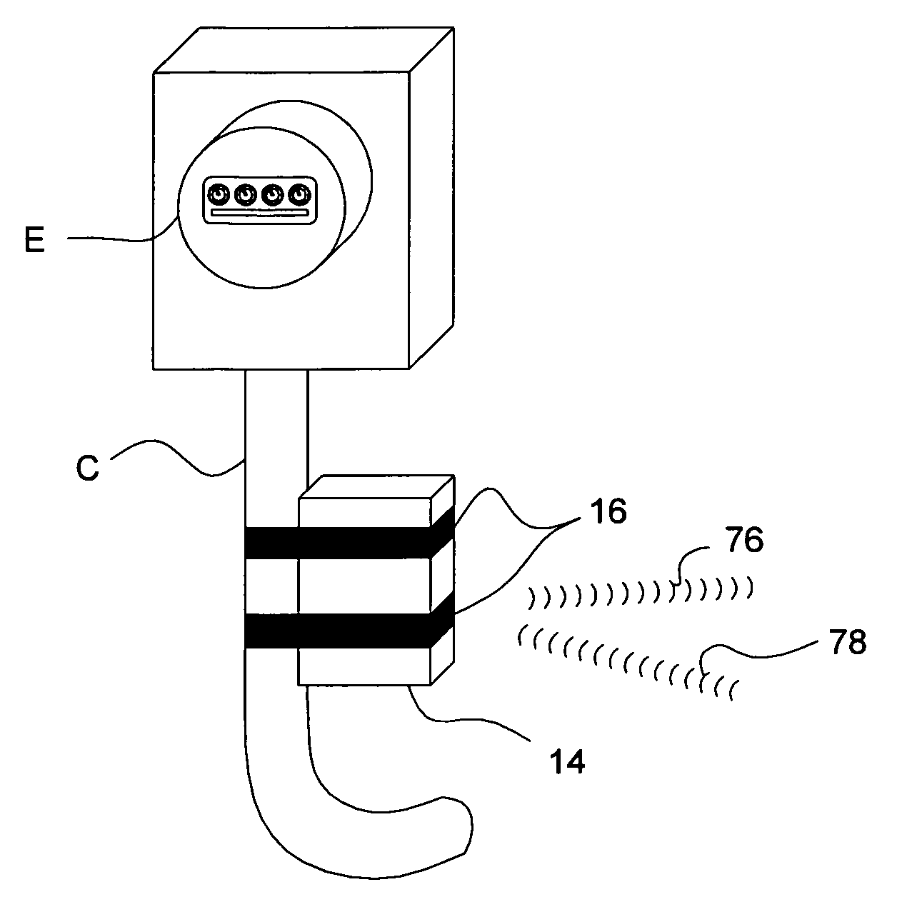
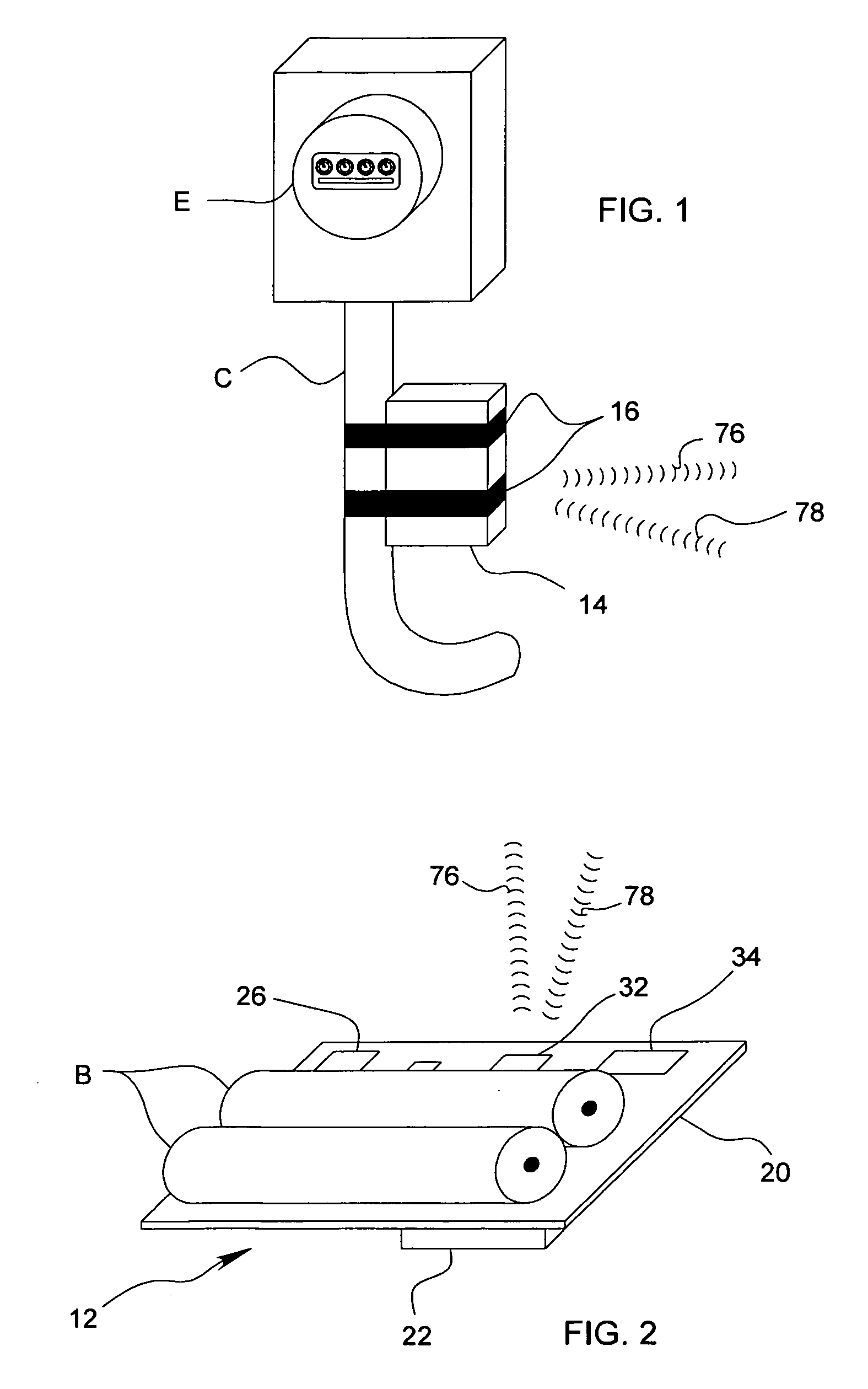
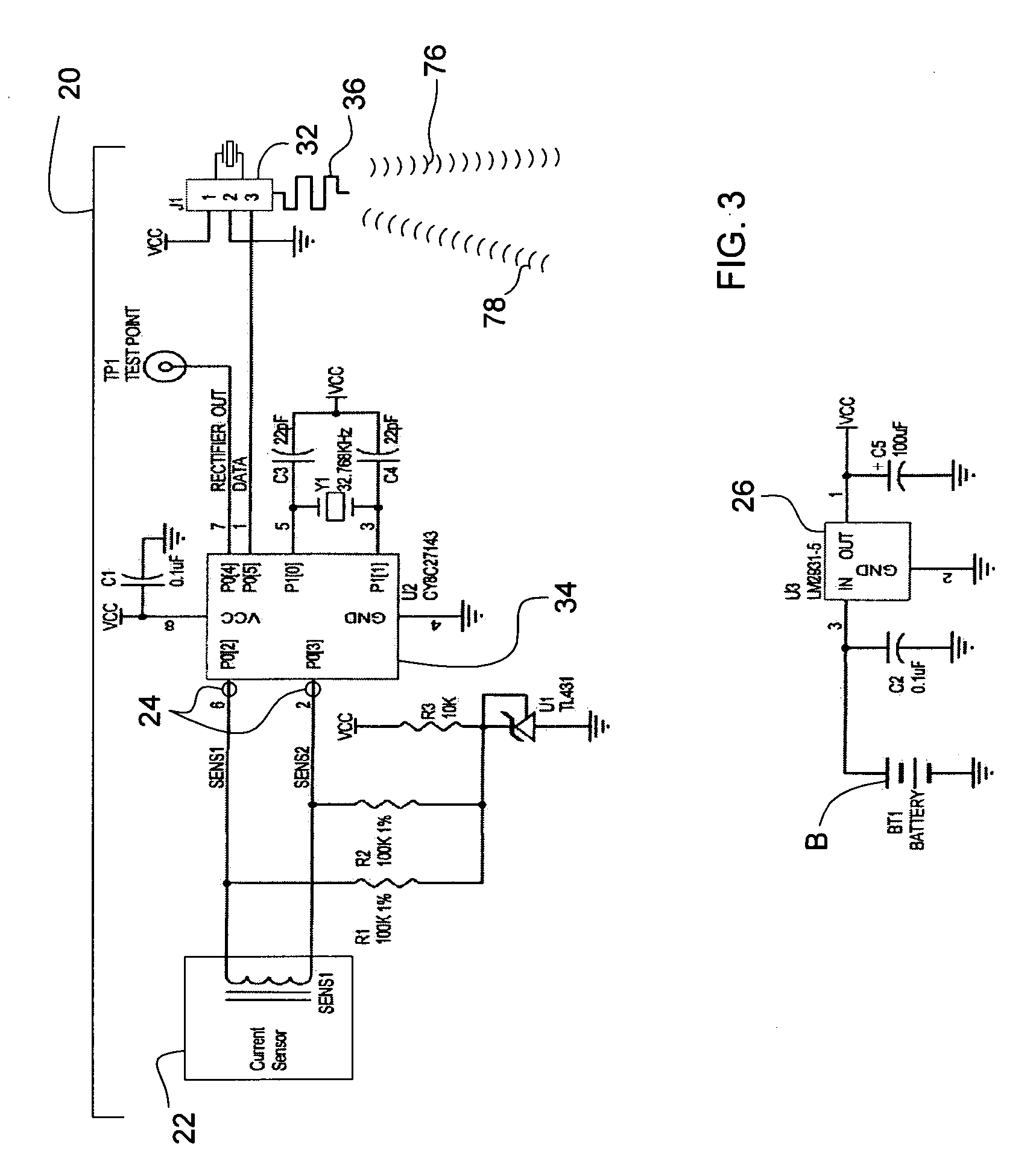
  • Method and apparatus for monitoring power consumption
  • Method and apparatus for monitoring power consumption
  • Method and apparatus for monitoring power consumption

Examples


Embodiment Construction

[0052]As used herein, the expression “CVT” means a current-to-voltage transformer, which is described in more detail elsewhere herein and in the above noted U.S. Pat. Nos. 4,717,872 and 4,754,218. The term “EMF” means electromagnetic force. The abbreviation “PROC” means programmable radio on a chip, which is a transceiver capable of bidirectional communications and which is described in more detail elsewhere herein. The term “PSOC” means programmable system on a chip and an example is described elsewhere herein. The term “RF” denotes the phraseradio frequency”.

[0053]Referring now to the various figures and illustrations, those skilled in the relevant arts should appreciate that each of the preferred, optional, and alternative embodiments of the inventive power consumption monitoring system 10 contemplates interchangeability with all of the various features, components, modifications, and variations illustrated throughout the written description, claims, and pictorial illustrations...


PUM


Abstract

A power consumption monitor, system, and method for monitoring power consumed by equipment, appliances, devices, buildings, and campuses is accomplished by passive sensors (12, 40) that detect power transmitted by individual conductors (C), and which include a current to voltage transformer with a passive, open-circuit electromagnetic force concentrator (22) positioned near the conductor (C). The sensor (22) generates an amplitude signal proportional to the power passing through the conductor (C). Programmable radios on a chip (32, 62, 72) and systems on a chip (34, 64, 74) are used to transmit the amplitude signal to a monitor (50) that displays the power being consumed along with actual and estimated cost and historical information. Software programs are implemented across the sensors (12, 40) and monitors (50) and a remote computer (80) to enable real-time monitoring power consumption with a resolution that spans from entire campuses down to single devices.

Description

PRIORITY CLAIM TO RELATED APPLICATION[0001]This application claims the benefit of the earlier priority filing date of commonly owned and co-pending U.S. Provisional Patent Application No. 60 / 924,833 filed Jun. 1, 2007, which was filed in the name of the sole and common inventor, Charles G. WAGNER, which is entitled METHOD AND APPARATUS FOR MONITORING POWER CONSUMPTION, and which is hereby incorporated by reference in its entirety as though fully set forth in the present application.BACKGROUND OF THE INVENTION[0002]1. Field of the Invention[0003]This invention relates to the field of devices, methods, and systems for monitoring electric power consumption of electrically powered appliances, devices, and equipment as well as power consumption of residential, commercial, and / or industrial buildings and facilities as well as organizational or business campuses of any size or configuration. The invention described herein further relates to a method and apparatus for the monitoring of elec...

Claims


Application Information

Patent Timeline
Patent Type & Authority Applications(United States)
IPC IPC(8): H04B17/00H04B1/16
CPCG01D4/008G01D21/00Y04S20/40Y04S20/46Y02B90/245G08C19/02G01R22/061G01R22/063G01D2204/18Y04S20/30Y02A90/10Y02B90/20
Inventor WAGNER, CHARLES G.
Owner POWERKUFF
Learn More