
Watch Winder

a winder and watch technology, applied in the direction of horology, instruments, coupling device connections, etc., can solve the problems of increasing purchase costs and relatively high manufacturing costs, and achieve the effect of reducing manufacturing costs and manufacturing costs

Active Publication Date: 2010-07-01
ABEST PRODS RESOURCING
View PDF12 Cites 28 Cited by
  • Summary
  • Abstract
  • Description
  • Claims
  • Application Information

AI Technical Summary

Benefits of technology

[0006]The primary objective of the present invention is to provide a watch winder comprising plural watch winder units that can be assembled to one another and electrically connected, so that it is unnecessary to dispose one power supply on the respective watch winder units to supply the power to the respective watch winder units of the watch winder, thus reducing manufacturing cost and satisfying environmental protection requirements.
[0007]In order to achieve the above objectives, a watch winder in accordance with the present invention comprises plural watch winder units each including at least one first connector and at least one second connector. The first connectors and the second connectors are all made of electrically-conductive material, and the first connector of one of the winder units is assembled in the second connector of the other of the winder units to electrically connect the two winder units, so that the plural watch winder units can be assembled and electrically connected to one another. By such arrangements, the assembled watch winder units only need one power supply, thus not only reducing the manufacturing cost but satisfying the environmental protection requirements. In addition, the watch winder units can be assembled as desired.

Problems solved by technology

Therefore, from the manufacturer angle, the manufacturing cost is relatively high, and from environmental angle, the conventional watch winders are not environmental-friendly, further from the consumer angle, the number of power supplies is large, thus not only increasing the purchase cost but possibly causing danger.

Method used


Image

  • Watch Winder
  • Watch Winder
  • Watch Winder

Examples


first embodiment

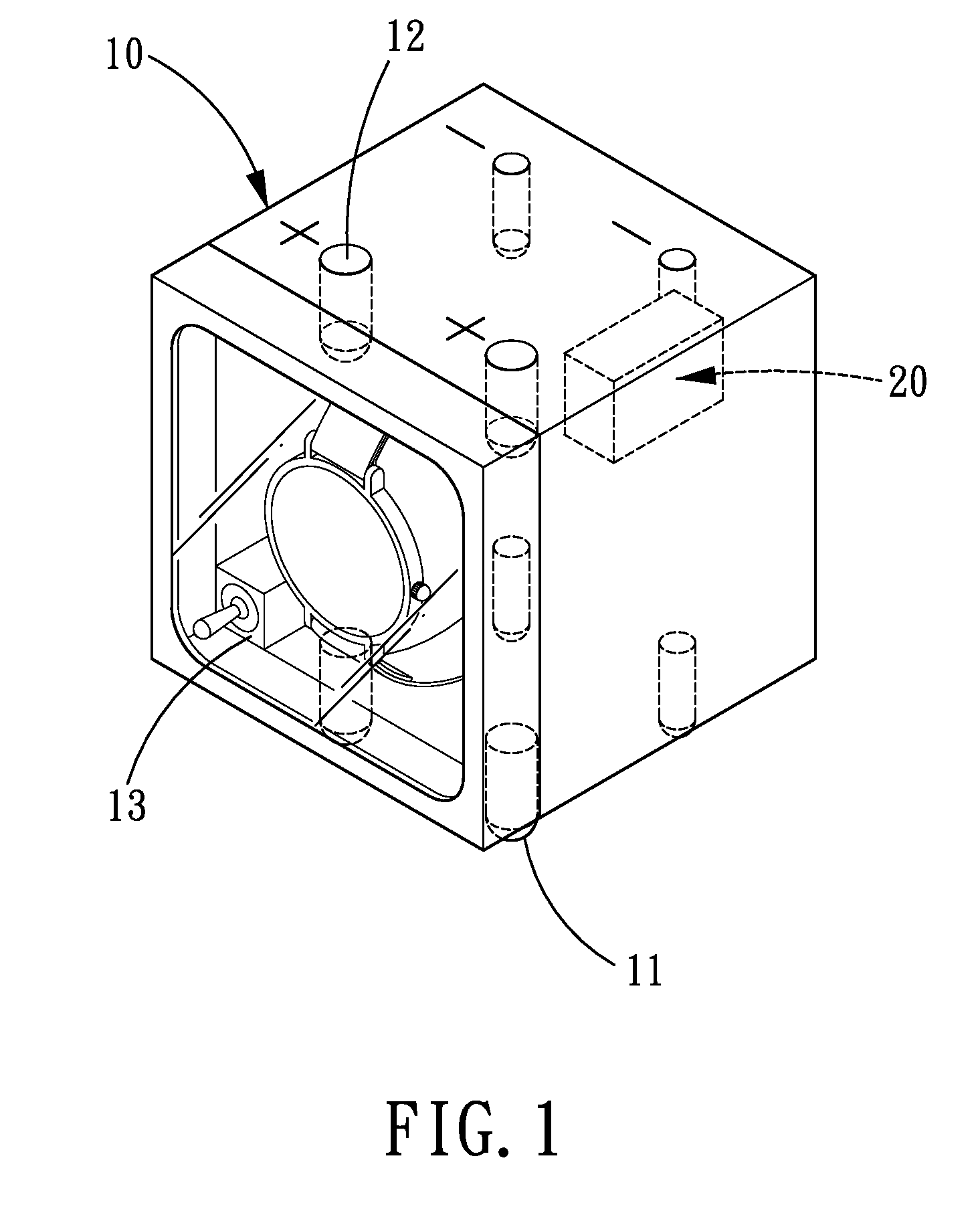
[0014]Referring to FIGS. 1-2, a watch winder in accordance with the present invention comprises plural watch winder units 10. Each of the watch winder units 10 includes four first raised connectors 11 that are located on one outer side thereof and four second concave connectors 12 that are located in another outer side thereof in alignment with the first connectors 11. The first connectors 11 and the second connectors 12 are all made of electrically-conductive material, such as copper or other metals, so that the first connectors 11 and the second connectors 12 are electrically conductive. As for the respective watch winder units, two of the four first connectors 11 are bigger than other two first connectors 11 in outer diameter, similarly, the two of the second connectors 12 which are in alignment with the two bigger-diameter first connectors 11 are correspondingly bigger in inner diameter than the other two second connectors 12. The first connectors 11 which have the same outer di...

second embodiment

[0017]Referring to FIGS. 3-4, a watch winder in accordance with the present invention further comprises a base 30 on which plural watch winder units 10 are assembled.

[0018]A width of the respective watch winder units 10 is L, a distance between the two first connectors 11 which have the same outer diameter of the respective watch winder units 10 and the distance between the two second connectors 12 which have the same inner diameter of the respective watch winder units 10 are both L / 2, and a distance from the first connectors 11 and the second connectors 12 to their respective neighboring side edges of the respective watch winder units 10 is L / 4. The respective watch winder units 10 include a power switch 13, and the first connectors 11 are assembled in the second connectors 12 to assemble the watch winder units 10 in such a manner that the watch winder units 10 are electrically connected to one another.

[0019]The base 30 is provided with plural concave third connectors 31 for assemb...


PUM


Abstract

A watch winder comprising plural watch winder units and a power supply. The plural watch winder units are assembled by connectors in such a manner that the watch winders units are electrically connected to one another, and the power supply is electrically connected to one of the watch winder units to supply power to all the electrically-connected watch winder units. By such arrangements, the respective watch winder units are not required to be provided with one power supply, thus saving the manufacturing cost, satisfying the requirements of environmental protection, and the watch winder units can be assembled as desired.

Description

BACKGROUND OF THE INVENTION[0001]1. Field of the Invention[0002]The present invention relates to a watch winder, and more particularly to a watch winder which can reduce the manufacturing cost and satisfy the environmental protection requirements through reduction of the number of power supplies.[0003]2. Description of the Prior Art[0004]Watch is not only one of the important inventions in the history of human but one of the indispensable tools in the modern daily life. The existing watches include two types: the modern common quartz watches and the early mechanical watches. Due to the advantages such as high accuracy and low price, the quartz watches have become more common today. In addition, some mechanical watches in which the interior mechanical components can produce power are also cherished by many people. Such mechanical watches must be manually wound by rotation of a stem or can be automatically wound up through the motion of the user's arm, in order to keep mechanical watc...

Claims


Application Information

Patent Timeline
Patent Type & Authority Applications(United States)
IPC IPC(8): G04C1/00
CPCG04B5/00G04D7/009
Inventor HUANG, WEN-HSIN
Owner ABEST PRODS RESOURCING
Learn More