
Apparatus and Method for Aiming a Surgical Tool

Active Publication Date: 2010-06-24
LOWER EXTREMITY INNOVATIONS
View PDF9 Cites 18 Cited by
  • Summary
  • Abstract
  • Description
  • Claims
  • Application Information

AI Technical Summary

Benefits of technology

[0005]Embodiments of the present invention address the need for an easy to use, mechanical apparatus that offers movement in multiple planes while guaranteeing, given proper placement of the leading end of a locator tool at a target (perhaps not discernibly located within a bone or within a joint), that the leading end of a second surgical tool be placed at precisely the same target. A surgical guide for aiming at least one tool toward a surgical target is provided in a first embodiment. The surgical guide has a base and at least one member that engages with the base. The base has a base thickness disposed orthogonal to and a base width disposed within a plane. A track is cut through the base thickness; the track has a uniform track width and a fixed curvature so as to define a base arc of a base circle. The base circle i

Problems solved by technology

For many procedures, surgeons must rely on cumbersome C-arm fluoroscopy in the operating room to confirm the location of hardware.
This, and other forms of intra-operative x-ray imaging, inevitably leads to excessive radiation exposure as well as increased operating times. There is a need for a single, easy to use, mechanical apparatus that offers movement in multiple planes while guaranteeing, given proper placement of the leading end of a first surgical tool (sometimes described herein as a locator tool) at a target (perhaps not discernibly located within a bone or within a joint), that the leading end of a second surgical tool be placed at precisely the same target.

Method used


Image

  • Apparatus and Method for Aiming a Surgical Tool
  • Apparatus and Method for Aiming a Surgical Tool
  • Apparatus and Method for Aiming a Surgical Tool

Examples


Embodiment Construction

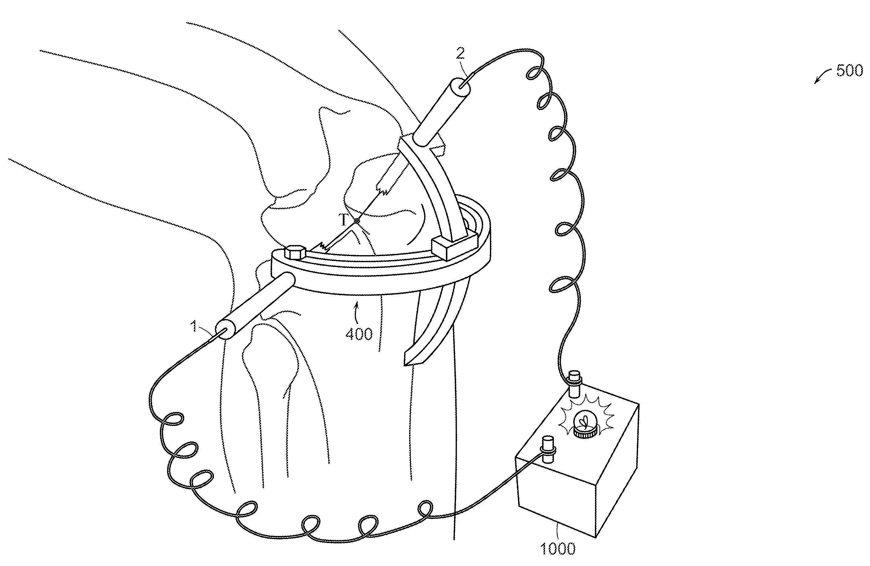
[0020]FIGS. 1(a) and 1(b) show a surgical site, in particular, that of a human foot and selected associated bones. Locator tool 1 has been drilled (or otherwise inserted) into the foot. The proximal end of locator tool 1 is lodged within bone at surgical target T. The surgeon wishes to install tool 2 such that its proximal end will also reside at surgical target T. The surgeon wishes to insure the accuracy of this placement without the use of ancillary equipment such as intra-operative x-ray imaging devices to accurately locate surgical target T.

[0021]Accurate placement of tool 2 is facilitated by the use of surgical guide 100. The embodiment of surgical guide 100 illustrated in FIGS. 1(a) and 1(b) has base 10 and member 20. Base 10 has track 11 cut through base thickness t. Track 11 is shown as having a uniform track width; track 11 also has a fixed curvature defining an arc of a base circle. Base 10 also has base channel 13 cut through base width W. Base channel 13 is sized to acc...


PUM


Abstract

An easy to use mechanical apparatus intended for aiming a surgical tool is provided. Embodiments of the apparatus offer movement in multiple planes while guaranteeing, given proper placement of the leading end of a locator tool at a target, that the leading end of a second tool be placed at precisely the same target. Methods of using the apparatus as well as kits including the apparatus are also provided.

Description

CROSS-REFERENCE TO RELATING APPLICATION(S)[0001]This application claims priority from U.S. Provisional Patent Application Ser. No. 61 / 203,245, filed Dec. 19, 2008, which is incorporated herein by reference.TECHNICAL FIELD[0002]The present invention relates to devices and procedures to facilitate accurate placement of hardware. More particularly, accurate positioning of surgical tools is assured through use of the methods and apparatus disclosed.BACKGROUND ART[0003]The effectiveness of most surgical procedures depends in large part on the accuracy with which hardware is introduced. Guide pin and drill guides are very useful in achieving improved accuracy of hardware placement.[0004]Many current guide or aiming models offer very limited range of motion Many are specifically designed for situations in which a target point is positioned within a more discernible intra-articular space rather than within a bone or other anatomical structure. For many procedures, surgeons must rely on cumb...

Claims


Application Information

Patent Timeline
IPC IPC(8): A61B17/56
CPCA61B17/17A61B17/1707A61B2017/1775A61B17/1764A61B17/1725A61B17/1775
Inventor HEILALA, MATT A.MUNOZ, AVERY B.STEINBERG, JOHN S.WEINRAUB, GLENN
Owner LOWER EXTREMITY INNOVATIONS
Learn More