
Quick Lubricant Nipple Mechanism with a Check Device

Inactive Publication Date: 2010-06-24
HIWIN MIKROSYST
View PDF5 Cites 4 Cited by
  • Summary
  • Abstract
  • Description
  • Claims
  • Application Information

AI Technical Summary

Benefits of technology

[0011]As compared to the conventional technology, the present invention has the following advantages:
[0012]Firstly, no matter the lubricant nipple of the present invention is located in any corner or gap of the machine table, the extension pipe device can extend the lubricant injection position to an open position outside the machine table where lubricant injection can be carried out quickly and easily without any spatial or visual obstacles.
[0013]Secondly, since the lubricant nipple of the present invention is connected to the extension pipe device, which makes it easier to align the lubricant gun, and the direction of the inlet connection can also be changed freely with user's action, so as to solve the problem of the conventional lubricant gun that the slide block is likely to falling off when it is pushed by the lubricant gun during lubricant injection. Hence, with the device of the present invention, the lubricant injection can be done by only one person.
[0014]Thirdly, the lubricant nipple and the extension pipe device which comprises the pipe, the outlet connection, the check valve and the inlet connection are all standardized structures and specifications without needing to be specially designed and molded, so that the cost is reduced.

Problems solved by technology

The abovementioned lubricant injection mechanism requires the lubricant gun to be forced into the lubricant nipple which is usually located inside the machine table, which makes the lubricant injection work difficult and makes it difficult for the user to apply force and to align the lubricant gun with the lubricant nipple.
In addition, the lubricant nipple is usually provided in a movable mechanism, so that when injecting lubricant, the lubricant injection operation requires the cooperation of two persons, naturally, it is very inconvenient.

Method used


Image

  • Quick Lubricant Nipple Mechanism with a Check Device
  • Quick Lubricant Nipple Mechanism with a Check Device
  • Quick Lubricant Nipple Mechanism with a Check Device

Examples


Embodiment Construction

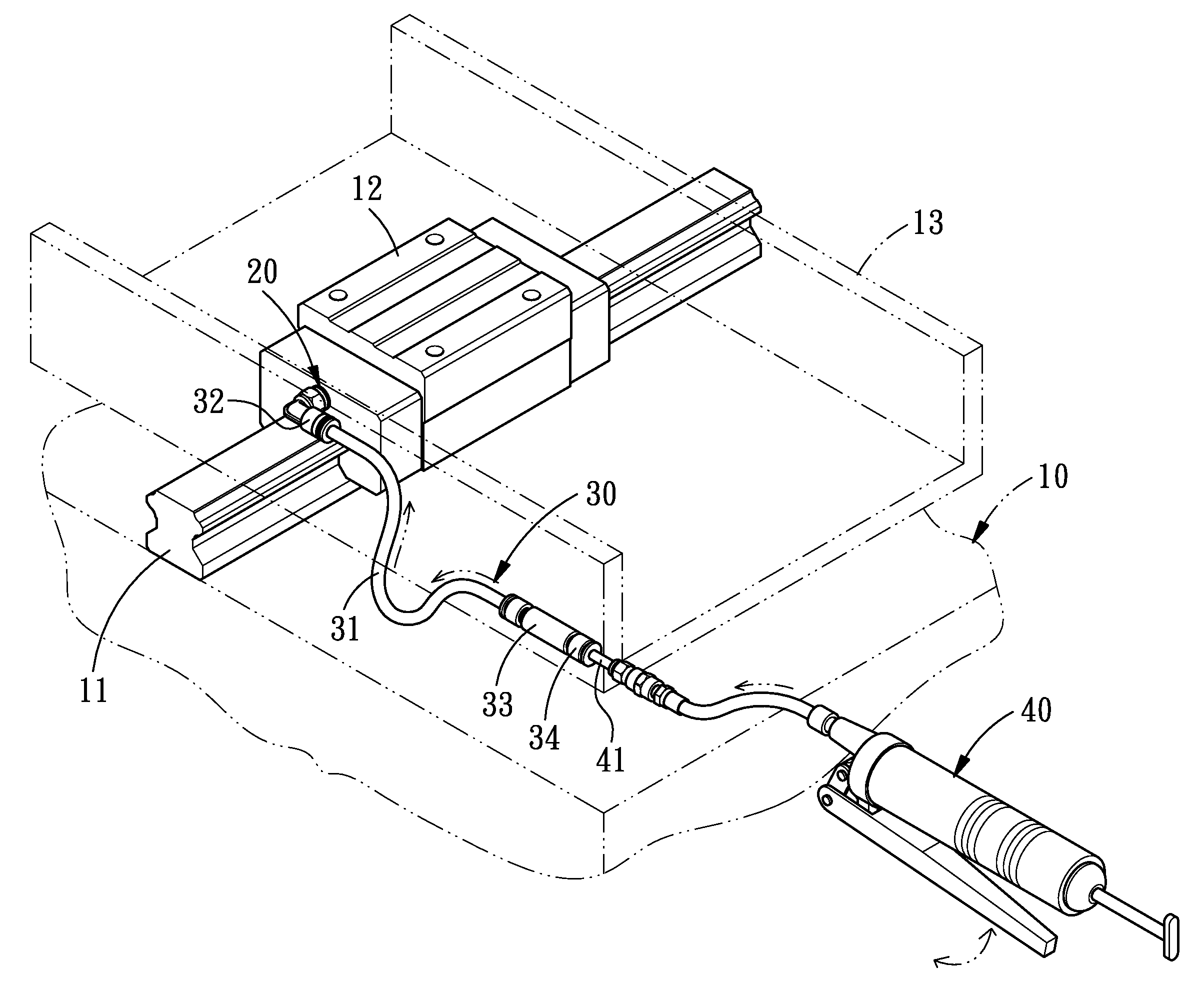
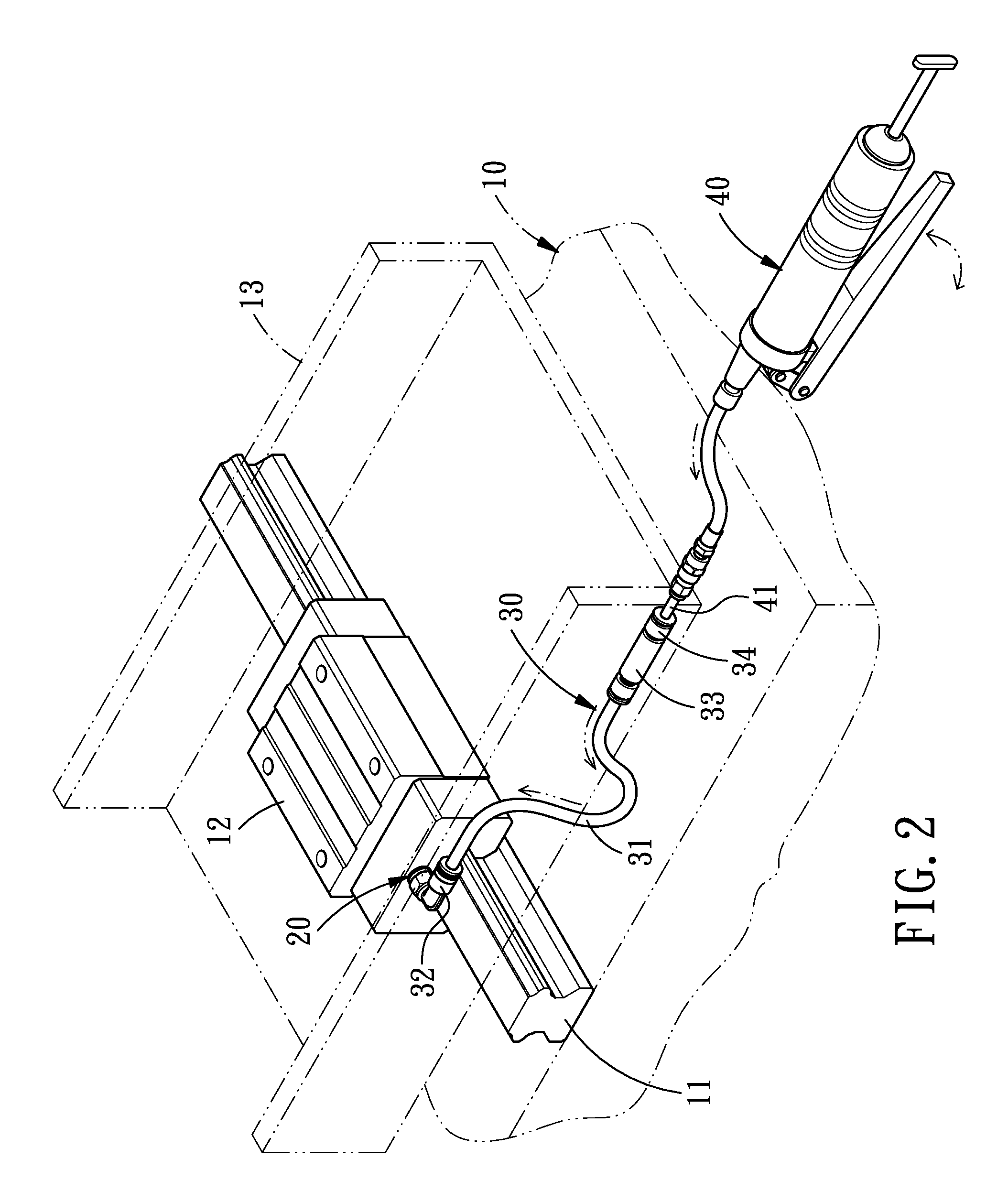
[0020]Referring to FIGS. 1 and 2, a quick lubricant nipple mechanism with a check device in accordance with the present invention comprises a machine table 10, a lubricant nipple 20, an extension pipe device 30 and a lubricant gun 40.

[0021]On the machine table 10 is provided a guide rail 11 on which is movably disposed a slide block 12 for carrying a movable seat 13 to move on the guide rail 11.

[0022]The lubricant nipple 20 is provided on the slide block 12 of the machine table 10.

[0023]The extension pipe device 30 comprises a pipe 31, an outlet connection 32, a check valve 33 and an inlet connection 34. The pipe 31 can be flexible or rigid and has one end connected to the outlet connection 32 and the other end connected to one end of the check valve 33 which has the other end connected to the inlet connection 34. The outlet connection 32 of the extension pipe device 30 is connected to the lubricant nipple 20, and through the pipe 31 of the extension pipe device 30, the check valve ...


PUM


Abstract

A quick lubricant nipple mechanism with a check device comprises a lubricant nipple which is connected to an extension pipe device having a pipe, an outlet connection, a check valve and an inlet connection. The pipe has one end connected to the outlet connection and the other end connected to one end of the check valve which has the other end connected to the inlet connection. The outlet connection of the extension pipe device is connected to the lubricant nipple, so that the lubricant injection can be carried out quickly and easily and the lubricant gun is easy to align. Hence, with such a device, the lubricant injection can be done by only one person.

Description

BACKGROUND OF THE INVENTION[0001]1. Field of the Invention[0002]The present invention relates to a quick lubricant nipple mechanism with a check device for injecting lubricant into moving or rolling parts of a mechanism, and more particularly to an improved lubricant injection structure which can inject lubricant quickly and easily.[0003]2. Description of the Prior Art[0004]Lubricant is usually used to prevent friction among various moving or rolling parts of a mechanism. To prevent loss of the lubricant and keep it from dust, the lubricant is usually contained in a sealing structure. However, the lubricant will still be used up gradually along with the rotation of the mechanism, so it must be supplied regularly to maintain the lubricating effect, and the current lubricant supplying method is to use a lubricant nipple to cooperate with a lubricant gun. However, the conventional lubricant nipple is usually located inside the mechanism, which makes the lubricant injection work difficu...

Claims


Application Information

Patent Timeline
IPC IPC(8): F16N21/02
CPCF16N21/04F16C29/00F16C29/0647F16C33/6622
Inventor CHOU, CHI-PINHSIEH, MING-HUNG
Owner HIWIN MIKROSYST
Learn More