Radio Base Station and Channel Allocation Information Transmission Method
a technology of channel allocation and information transmission, which is applied in the direction of transmission monitoring, frequency-division multiplex, wireless commuication services, etc., can solve the problems that the radio communication terminal might not be able to receive any of the bcch and the pcch, and achieve the improvement of the acquisition probability of map (channel allocation information), the effect of improving the utilization efficiency of downlink frames and receiving channel allocation information more reliably
- Summary
- Abstract
- Description
- Claims
- Application Information
AI Technical Summary
Benefits of technology
Problems solved by technology
Method used
Image
Examples
first embodiment
Overall Schematic Configuration of Mobile Communication System
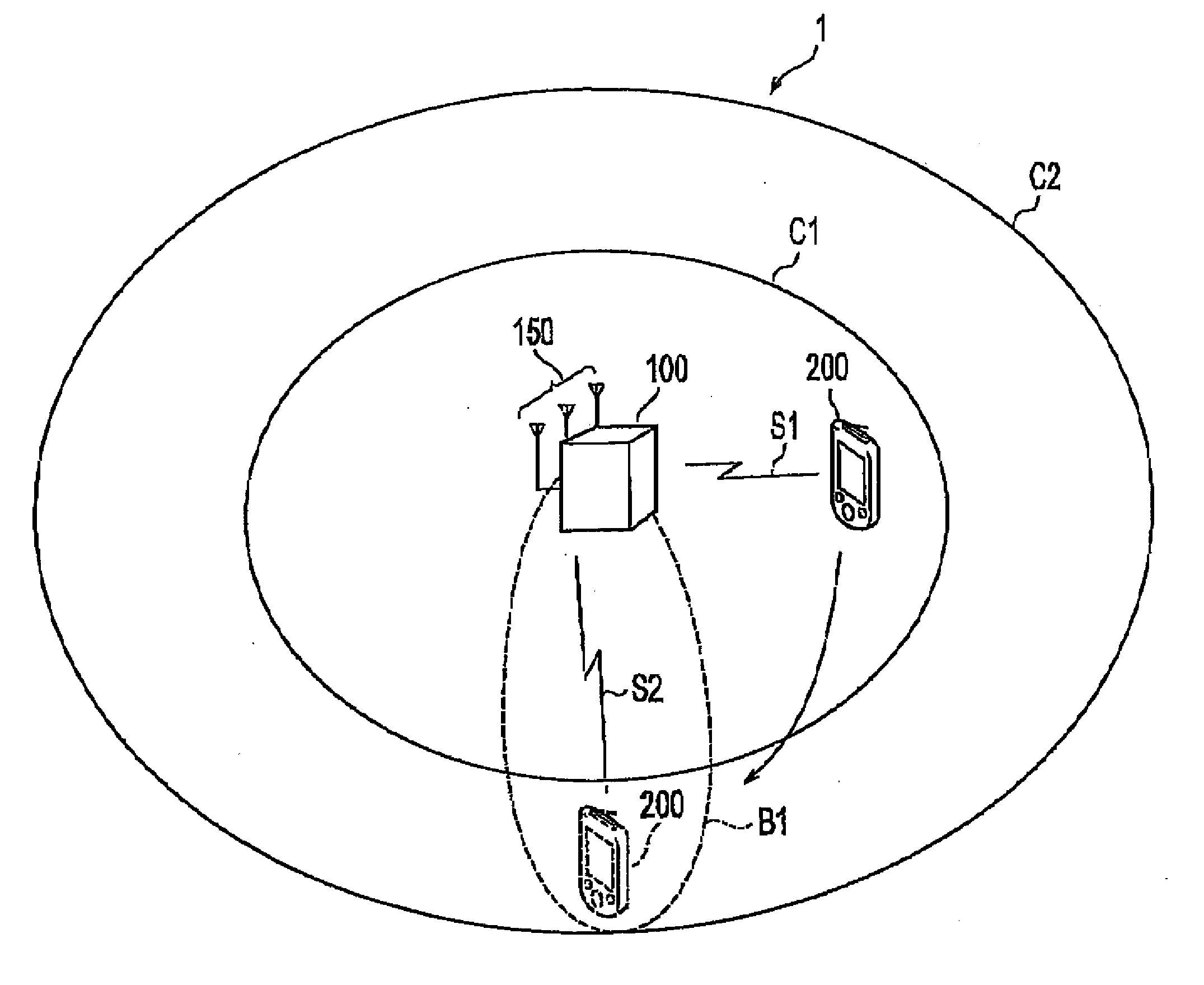
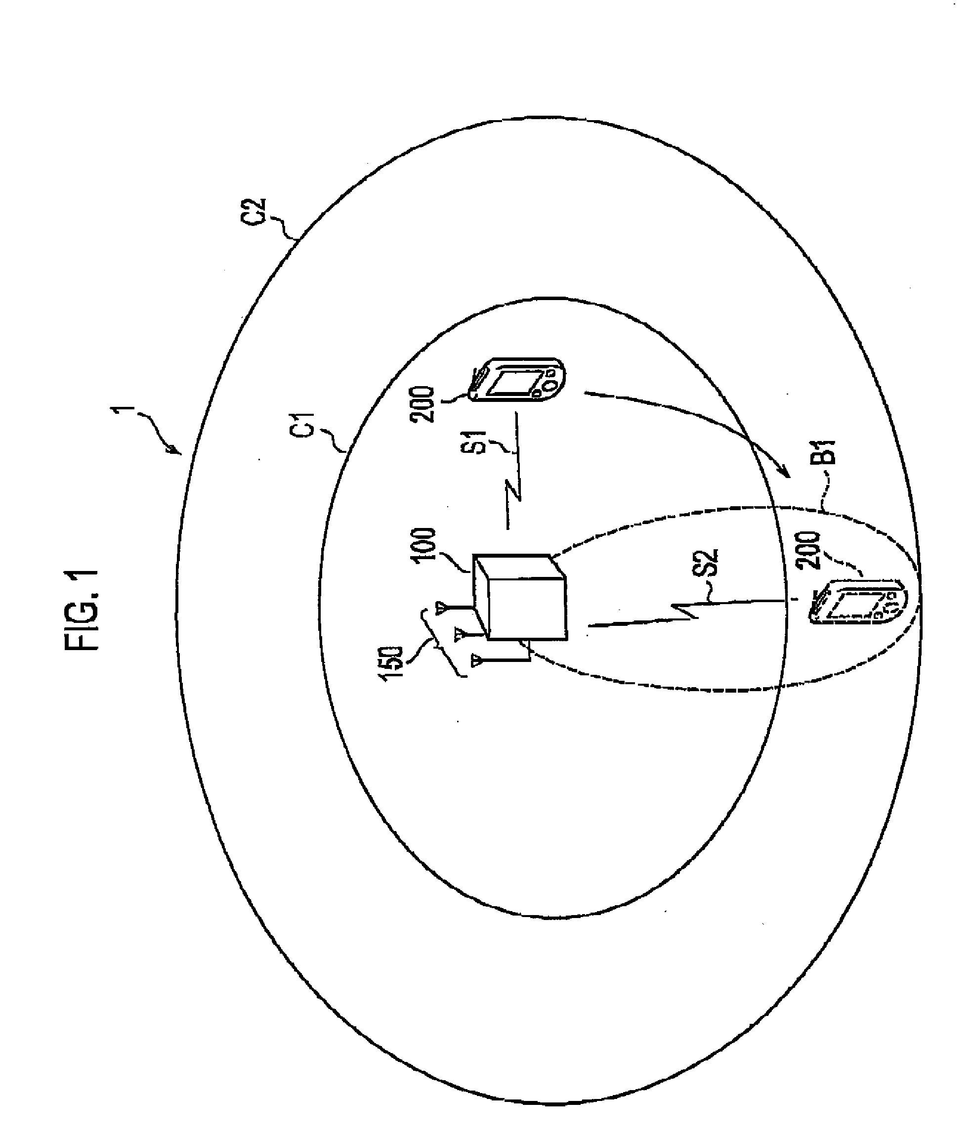
[0044]FIG. 1 shows an overall schematic configuration of a mobile communication system 1 according to this embodiment. The mobile communication system 1 includes a radio base station 100 and radio communication terminals 200. Note that the number of radio base stations and the number of radio communication terminals included in the mobile communication system 1 are not limited to those shown in FIG. 1.
[0045]The mobile communication system 1 is based on mobile WiMAX specified in IEEE 802.16e. In this embodiment, the radio base station 1 is configured to transmit radio signals S1 and S2 based on orthogonal frequency-division multiplexing (OFDM) to the radio communication terminals 200.
[0046]The radio base station 100 includes an array antenna 150, and is thus capable of transmitting the radio signal S2 by using a directional beam B1. In addition, the radio base station 100 is also capable of transmitting the radio signal S1...
second embodiment
[0111]Next, a second embodiment of the present invention will be described. A conventional channel allocation information transmission, method has the following problems. Specifically, since a radio base station is configured to transmit channel allocation information by using both a BCCH and a PCCH, the channel allocation information transmitted by using either of these channels is left unused. This leads to problems such as deteriorating usage efficiency of downlink frames.
[0112]Here, when the radio communication terminal moves from the inside of a cell reached by a PCCH (hereinafter referred to as PCCH's reaching cell) into a BCCH's reaching cell formed inside the PCCH's reaching cell, the radio communication terminal becomes capable of receiving a BCCH that is transmitted for general radio communication terminals by using an omnidirectional beam. In this case in particular, channel allocation information included in the PCCH transmitted for a specified radio communication termin...
example 1
(1) Operation Example 1
[0151]FIG. 11 shows an operational flow in which the radio base station 1100 cancels transmission of a private MAP, and puts channel allocation information for the radio communication terminal 1200 in a broadcast map.
[0152]As shown FIG. 11, in step S1010, the radio base station 1100 and the radio communication terminal 1200 perform synchronous processing. By performing this synchronous processing, the radio communication terminal 1200 becomes capable of receiving downlink frames transmitted by the radio base station 1100.
[0153]In step S1020, the radio base station 1100 transmits a private MAP to the radio communication terminal 1200 by using the directional beam.
[0154]In step S1030, the radio bass station 1100 and the radio communication terminal 1200 perform ranging processing. Specifically, based on allocation information of a ranging channel included in the private MAP, the radio communication terminal 1200 performs processing such as adjusting timing of up...
PUM
 Abstract
Description
Claims
Application Information
 - R&D
- Intellectual Property
- Life Sciences
- Materials
- Tech Scout
- Unparalleled Data Quality
- Higher Quality Content
- 60% Fewer Hallucinations
Browse by: Latest US Patents, China's latest patents, Technical Efficacy Thesaurus, Application Domain, Technology Topic, Popular Technical Reports.
© 2025 PatSnap. All rights reserved.Legal|Privacy policy|Modern Slavery Act Transparency Statement|Sitemap|About US| Contact US: help@patsnap.com


