
Electronic assembly for attachment to a fabric substrate, electronic textile, and method of manufacturing such an electronic textile

Inactive Publication Date: 2010-06-17
SIGNIFY HLDG BV
View PDF15 Cites 18 Cited by
  • Summary
  • Abstract
  • Description
  • Claims
  • Application Information

AI Technical Summary

Benefits of technology

[0010]In view of the above-mentioned and other drawbacks of the prior art, a general object of the present invention is to provide an improved electronics assembly for attachment to a fabric substrate, in particular facilitating individual control of each of a plurality of electronic devices attached to a fabric substrate.

Problems solved by technology

A problem facing the developers of advanced electronic textiles is how to interconnect electronic devices with each other and with a power source via conductors provided on the fabric substrate of the electronic textile.
A drawback of this securing assembly is that individual control and addressing of each of a plurality of electronic devices appears very difficult to achieve, if at all possible.

Method used


Image

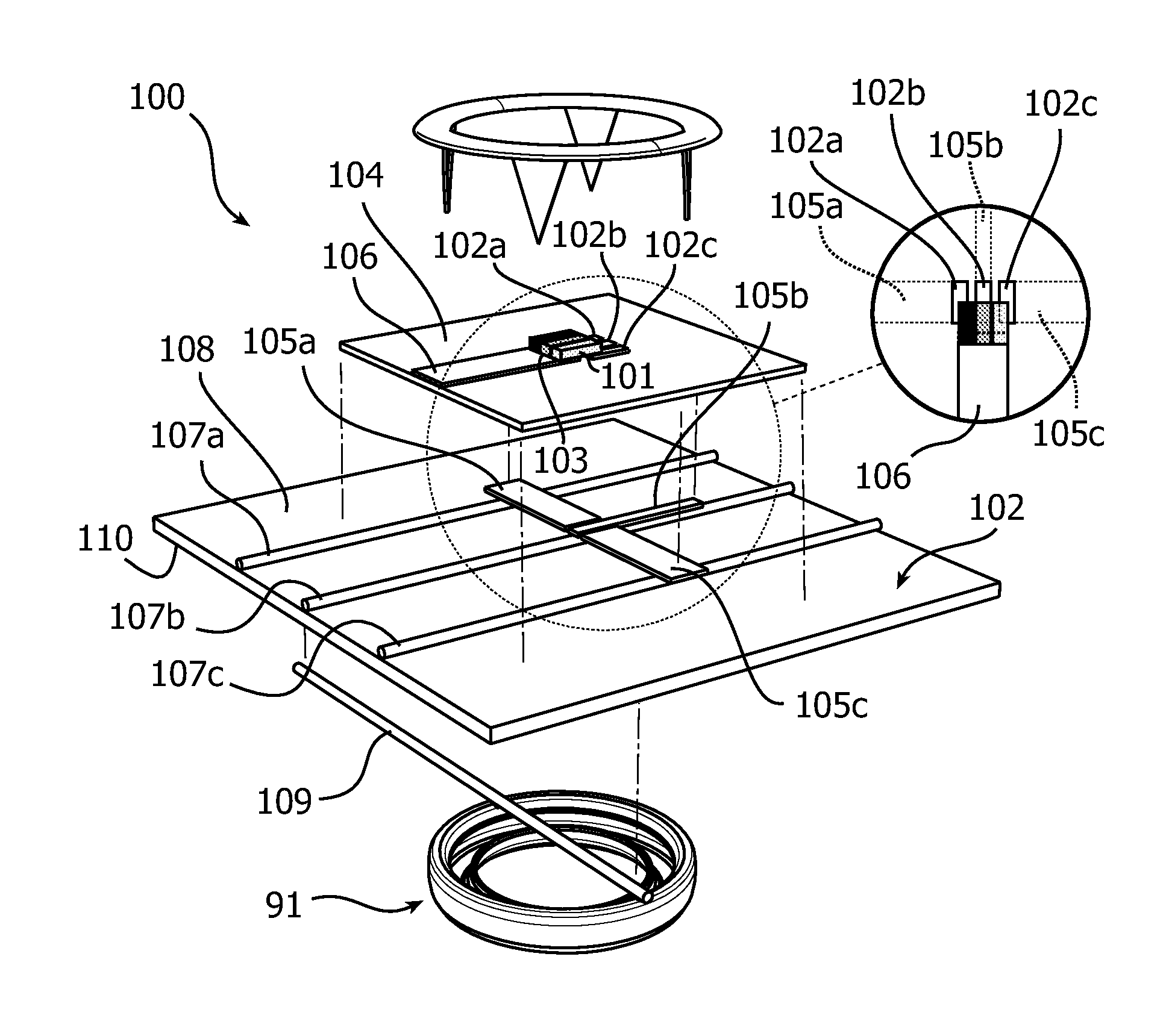
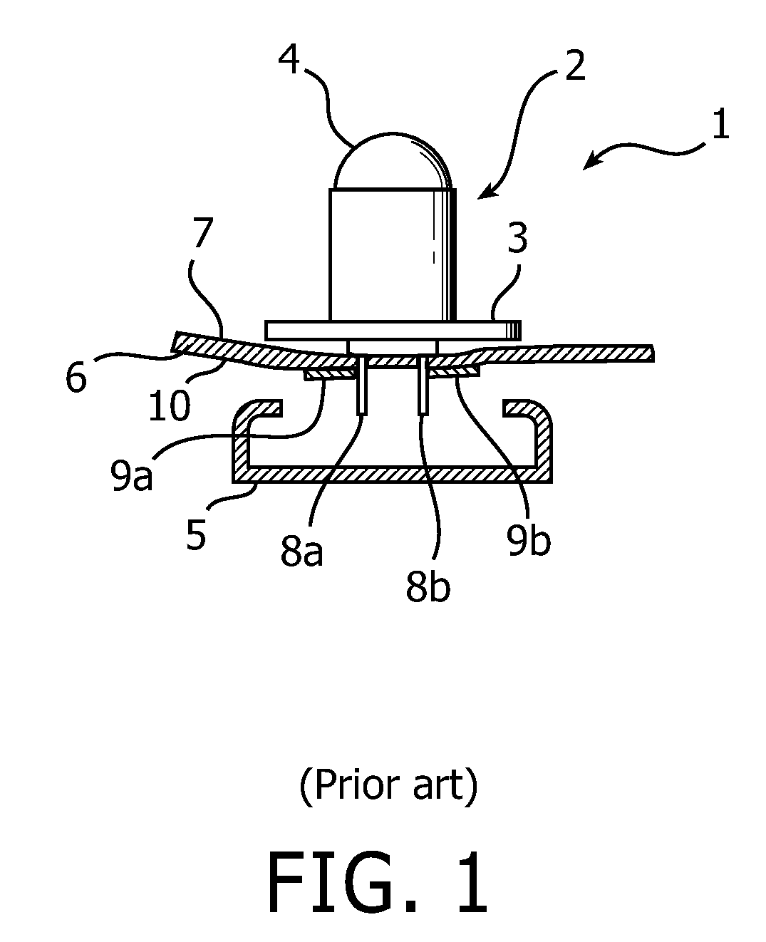
  • Electronic assembly for attachment to a fabric substrate, electronic textile, and method of manufacturing such an electronic textile
  • Electronic assembly for attachment to a fabric substrate, electronic textile, and method of manufacturing such an electronic textile
  • Electronic assembly for attachment to a fabric substrate, electronic textile, and method of manufacturing such an electronic textile

Examples


Embodiment Construction

[0069]In the following description, the present invention is mainly described with reference to an electronic assembly for attachment to a fabric substrate including one or several light-emitting diodes (LEDs).

[0070]It should be noted that this by no means limits the scope of the invention, which is equally applicable to such electronic assemblies comprising any other suitable electronic device, such as a sensor, processing circuitry, a memory module, a radio transmitter / receiver etc.

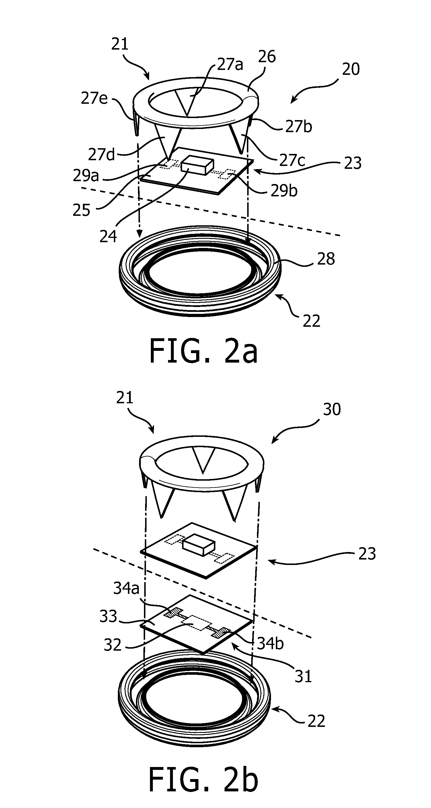
[0071]FIGS. 2a-b schematically illustrate two exemplary embodiments of the electronic assembly according to the invention, where the electronic device(s) is / are provided separately from the clamping members.

[0072]In FIG. 2a, an electronic assembly 20 is shown, having a first clamping member 21, a second clamping member 22, and an electronic device 23 in the form of an electronic component 24 mounted on a circuit board carrier 25. Terminals (not shown) of the electronic component are electrically connect...


PUM


Abstract

An electronic assembly (20; 30; 40; 50) for attachment to a fabric substrate (60; 82, 102) having a conductor pattern (62a-b; 85a-b; 107a-c) on a first side (63; 86; 108) thereof. The electronic assembly comprises an electronic device (23; 42; 64), and at least a first clamping member (21; 41; 65). The electronic assembly is, furthermore, adapted to clamp the electronic device (23; 42; 64) to the first side (63; 86; 108) of the fabric substrate (60; 82, 102) in such a way that the electronic device (23; 23 42; 64) is electrically connected to the conductor pattern (62a-b; 85a-b; 107a-c).

Description

TECHNICAL FIELD OF THE INVENTION[0001]The present invention relates to an electronic assembly for attachment to a fabric substrate having a conductor pattern on a first side thereof, comprising an electronic device, and at least a first clamping member, and an electronic textile comprising a fabric substrate and such an electronic assembly attached thereto.[0002]The present invention further relates to a method for manufacturing such an electronic textile.TECHNICAL BACKGROUND[0003]Currently, research in the field of electronic textiles is very active, and although not a great deal of advanced electronic textile products can be found in the market-place today, it is expected that many new products will find their way to the consumers in the near future.[0004]A problem facing the developers of advanced electronic textiles is how to interconnect electronic devices with each other and with a power source via conductors provided on the fabric substrate of the electronic textile. Furtherm...

Claims


Application Information

Patent Timeline
IPC IPC(8): H05K7/00H05K13/00A41D1/00
CPCA41D1/002H01R4/58H01R12/613H05K1/00H05K1/038Y10T29/49002H05K2201/029H05K2201/10393H01R4/06H05K1/189H05K2201/10106H05K3/325H01R12/61H01R43/00
Inventor BIESHEUVEL, MARKKRANS, MARTIJNBHATTACHARYA, RABIN
Owner SIGNIFY HLDG BV
Learn More