
Protector

Inactive Publication Date: 2010-06-17
SUMITOMO WIRING SYST LTD
View PDF6 Cites 30 Cited by
  • Summary
  • Abstract
  • Description
  • Claims
  • Application Information

AI Technical Summary

Benefits of technology

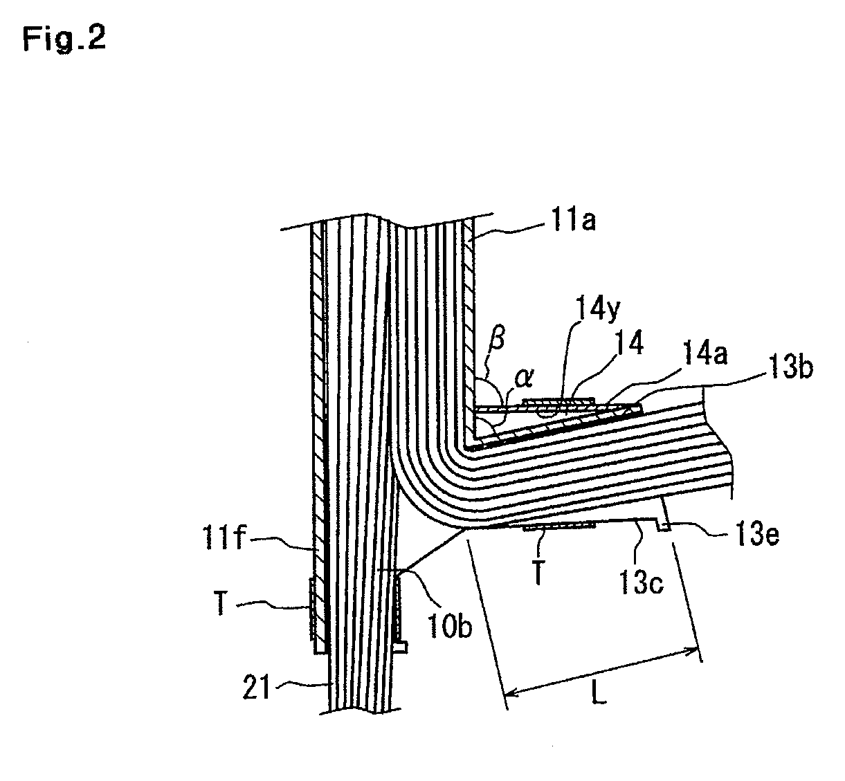
[0028]As described above, because in the present invention, the auxiliary wall for tape-winding use is projected from the protector body almost orthogonally thereto, it is possible to make the tape-winding direction approximately orthogonal to the side wall of the protector body. Therefore the tape coil does not contact the protector body at a tape-winding time, and the tape-winding operation can be performed easily. Thus a burden to be imposed on the operator can be reduced.
[0029]Further because the tape can be wound round the branch-wire branching portion and the branch wires approximately orthogonally thereto, the tape does not wrinkle and the branch wires can be firmly fixed to the branch-wire branching portion.
[0030]Further by forming the rib for tape-winding use projectingly from the auxiliary wall for tape-winding use along the tape-winding direction, there is an increase in the area of contact between the tape and the auxiliary wall for tape-winding use. Therefore even though the tape is firmly wound round the branch-wire branching portion, the tape is not broken by the edge of the auxiliary wall for tape-winding use.

Problems solved by technology

Therefore an operator's hand holding the tape coil TC strikes the protector body 2, which makes it difficult to perform a tape-winding operation.
To perform the tape-winding operation without wrinkling the tape T, the operator is required to pay close attention, which imposes a burden on the operator.

Method used


Image

  • Protector
  • Protector
  • Protector

Examples


Embodiment Construction

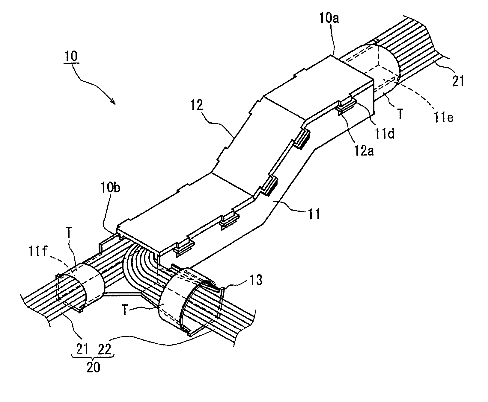
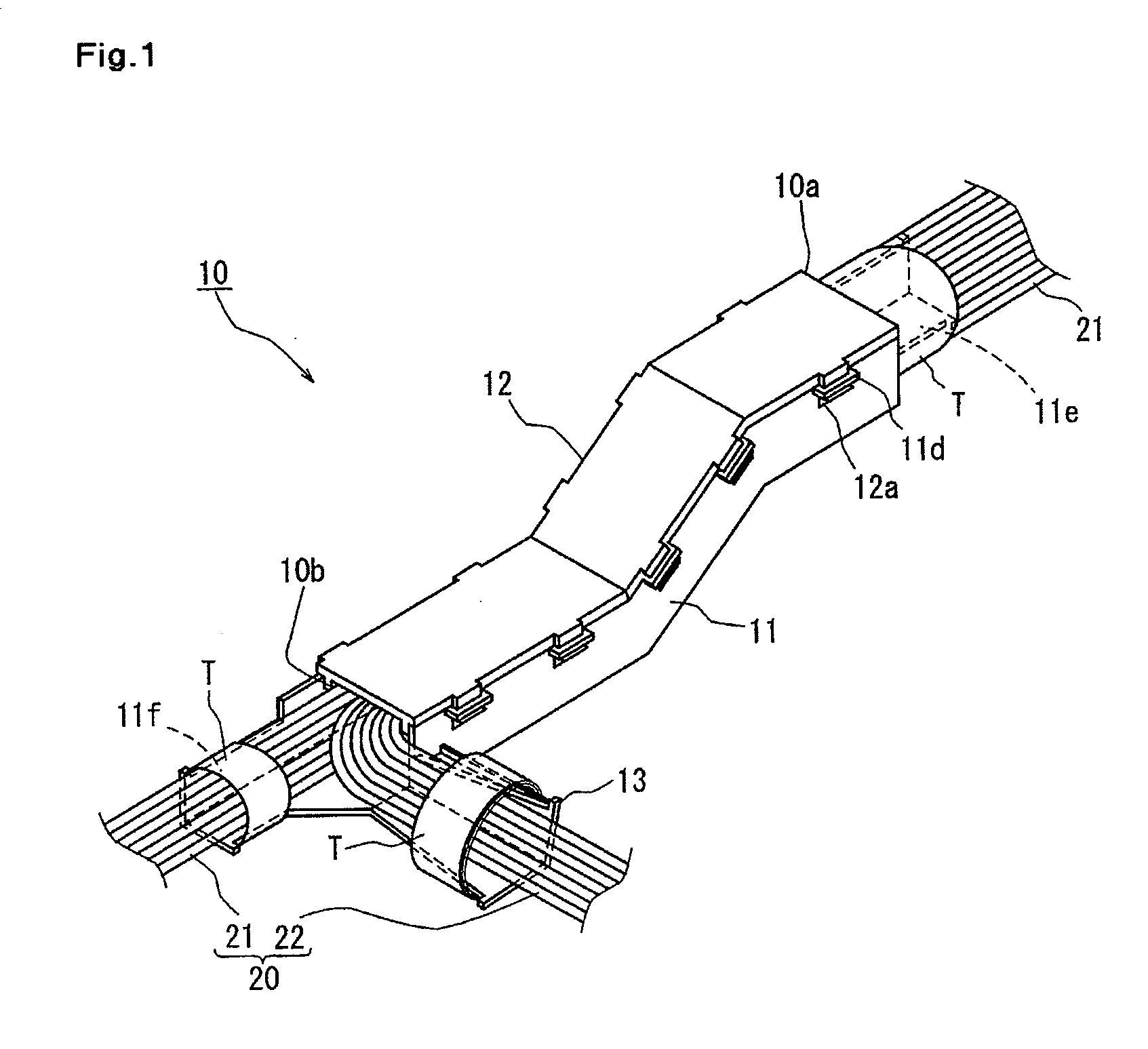
[0054]An embodiment of the present invention will be described below with reference to FIGS. 1 through 4.

[0055]In a protector 10 of the present invention, a group of electric wires composing trunk wires 21 of a wire harness 20 is penetrated through the protector 10, and branch wires 22 are branched off the trunk wires 21.

[0056]The protector 10 has a protector body 11 made of resin molding and a cover 12 to be placed on the protector body 11.

[0057]As shown in FIGS. 1 and 2, the trunk wires 21 are inserted through the protector body 11 from a one-end opening 10a, and the branch wires 22 are branched off the trunk wires 21 at an other-end opening 10b.

[0058]The protector body 11 has the shape of a trough open at its upper end and is curved in the shape of approximately a letter S from a trunk-wire insertion side toward a branch-wire branching side. At an edge of the protector body 11 disposed at an upper-end opening thereof, frame portions 11d to which claw portions 12a of the cover 12...


PUM


Abstract

In a protector, made of resin molding, through which a group of electric wires is penetrated, a branch-wire branching portion is projected slantly from a trough-shaped protector body along a direction in which the branch wires are wired, and the branch-wire branching portion has a bottom wall and one side wall and is sectionally L-shaped, and an auxiliary wall for tape-winding use is projected from an outer surface of the one side wall of the branch-wire branching portion with the auxiliary wall for tape-winding use forming an angle in a range of 90 degrees±20 degrees to the protector body.In the above-described construction, with branch wires inserted through the branch-wire branching portion, a tape is wound round peripheral surfaces of the branch wires, a peripheral surface of the branch-wire branching portion, and a periphery of the auxiliary wall for tape-winding use to fix the branch wires to the branch-wire branching portion.

Description

TECHNICAL FIELD[0001]The present invention relates to a protector which is mounted on a group of electric wires (wire harness) wired on a car. More particularly, in a protector which has a branch-wire branching portion projected from the body thereof, the present invention is intended to improve operability in winding a tape for branch-wire fixing use round branch wires and the branch-wire branching portion to fix the branch wires to the branch-wire branching portion.BACKGROUND ART[0002]A wire harness is wired on a car with the wire harness inserted into a protector which is a resin molding to protect the wire harness from external interfering members and restrict the wiring line of the wire harness.[0003]There is a case in which the wire harness inserted into the protector is connected to electric apparatuses mounted on a vehicle body by branching branch wires off trunk wires at a necessary position. At the branching position of the branch wires, by winding a tape round the branche...

Claims


Application Information

Patent Timeline
IPC IPC(8): H02G3/06H05K13/00
CPCB60R16/0215Y10T29/49002H02G3/0437
Inventor SUZUKI, TAKASHI
Owner SUMITOMO WIRING SYST LTD
Learn More