
Method for dissipating heat produced in scan head assembly of imaging apparatus

a technology of imaging apparatus and scan head, which is applied in the field of dissipating heat produced in the scan head assembly of the imaging apparatus, can solve the problems of increasing heat generation, temperature rise and heat produced within the flatbed enclosure may not be easily dissipated, and achieve the effect of dissipating heat produced

Active Publication Date: 2010-06-10
LEXMARK INT INC
View PDF6 Cites 9 Cited by
  • Summary
  • Abstract
  • Description
  • Claims
  • Application Information

AI Technical Summary

Benefits of technology

[0012]In view of the foregoing disadvantages inherent in the prior art, the present disclosure provides a method for dissipating heat produced in a scan head assembly of an imaging apparatus by including all the advantages of the prior art and overcoming the drawbacks inherent therein.

Problems solved by technology

More illumination of the media sheets requires operating the lamp at a higher power, which leads to generation of more heat.
Therefore, during the high speed scanning, there may result a temperature rise within the flatbed enclosure due to generation of more heat by the lamp.
Further, a conventional flatbed enclosure is generally sealed to prevent entry of contaminants into the flatbed enclosures and accordingly, the heat produced within the flatbed enclosures may not be easily dissipated therefrom, thereby leading to a further rise in the temperature.
A rise in temperature within the flatbed enclosure may result in rise in temperature of the scan head assembly.
The working efficiency of the scan head assembly may be affected due to high temperature thereof, thereby resulting in decreased quality of scanning of the media sheets.
Moreover, a prolonged exposure of the scan head assembly to a high temperature may result in shortening of life span thereof.
Moreover, inclusion of such cooling mechanisms may not be cost-effective and may increase an overall operating and maintenance cost of the imaging apparatus.

Method used


Image

  • Method for dissipating heat produced in scan head assembly of imaging apparatus
  • Method for dissipating heat produced in scan head assembly of imaging apparatus
  • Method for dissipating heat produced in scan head assembly of imaging apparatus

Examples


Embodiment Construction

[0024]It is to be understood that the disclosure is not limited in its application to the details of construction and the arrangement of components set forth in the following description or illustrated in the drawings. The disclosure is capable of other embodiments and of being practiced or of being carried out in various ways. Also, it is to be understood that the phraseology and terminology used herein is for the purpose of description and should not be regarded as limiting. The use of “including,”“comprising,” or “having” and variations thereof herein is meant to encompass the items listed thereafter and equivalents thereof as well as additional items. Unless limited otherwise, the terms “connected,”“coupled,” and “mounted,” and variations thereof herein are used broadly and encompass direct and indirect connections, couplings, and mountings. In addition, the terms “connected” and “coupled” and variations thereof are not restricted to physical or mechanical connections or couplin...


PUM


Abstract

Disclosed are a method and a computer program product for dissipating heat produced in a scan head assembly of an imaging apparatus during scanning of media sheets in the imaging apparatus. The method includes determining at least one of a temperature of the scan head assembly and a media sheet scan count. The method further includes moving the scan head assembly between a first position of the scan head assembly and a second position of the scan head assembly for dissipating heat, based on at least one of the temperature of the scan head assembly and the media sheet scan count.

Description

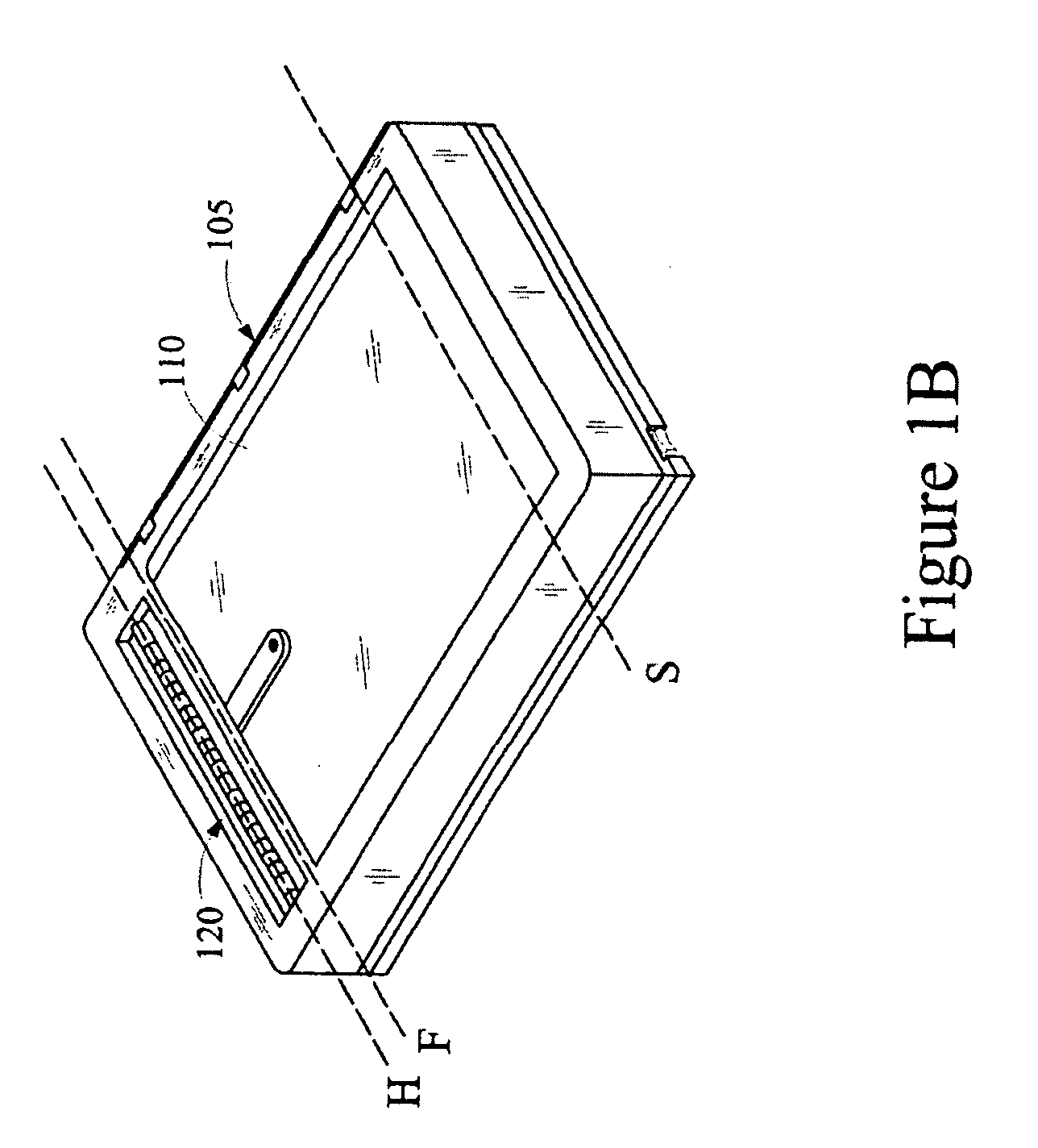
CROSS REFERENCES TO RELATED APPLICATIONS[0001]None.STATEMENT REGARDING FEDERALLY SPONSORED RESEARCH OR DEVELOPMENT[0002]None.REFERENCE TO SEQUENTIAL LISTING, ETC.[0003]None.BACKGROUND[0004]1. Field of the Invention[0005]The present invention relates generally to imaging apparatuses, and more particularly to a method for dissipating heat produced in a scan head assembly of an imaging apparatus.[0006]2. Description of the Related Art[0007]Imaging apparatuses, such as document scanners, are widely used for scanning printed media sheets and generating a digital image thereof. A conventional imaging apparatus includes a flatbed enclosure having a transparent board disposed on an open top end of the flatbed enclosure, and a scan head assembly disposed within the flatbed enclosure. The scan head assembly comprises a lamp, a plurality of mirrors, a plurality of lenses and a Charge Coupled Device (CCD). For carrying out scanning of a media sheet, the media sheet is placed on the transparent ...

Claims


Application Information

Patent Timeline
Patent Type & Authority Applications(United States)
IPC IPC(8): H04N1/04
CPCH04N1/00814H04N1/00832H04N1/00978H04N2201/0081H04N1/1017H04N1/193H04N1/00981
Inventor CUI, CHENGWULANGREL, CHARLES BRANDON
Owner LEXMARK INT INC
Learn More