
Image Sensor with Integrated Light Meter for Controlling Display Brightness

a technology of image sensor and light meter, which is applied in the field of image sensors, can solve the problems of increasing the cost, space and complexity of the device design, and reducing the use of image sensors. the effect of reducing the system cost and spa

Inactive Publication Date: 2010-06-10
HIMAX IMAGING LIMITED
View PDF3 Cites 41 Cited by
  • Summary
  • Abstract
  • Description
  • Claims
  • Application Information

AI Technical Summary

Benefits of technology

[0012]In view of the foregoing, it is an object of the present invention to provide a method and apparatus for an image sensor to automatically adjust the display brightness based on the ambient light in the environment, while reducing system cost and space, as well as attenuating substantial power consumption.

Problems solved by technology

As image sensors consume substantially more power than discrete photo sensors, image sensors are seldomly used, if at all, for controlling the backlight particularly in portable electronic devices or battery-operated devices.
This solution increases the cost, space and complexity of the device design.

Method used


Image

  • Image Sensor with Integrated Light Meter for Controlling Display Brightness
  • Image Sensor with Integrated Light Meter for Controlling Display Brightness
  • Image Sensor with Integrated Light Meter for Controlling Display Brightness

Examples


Embodiment Construction

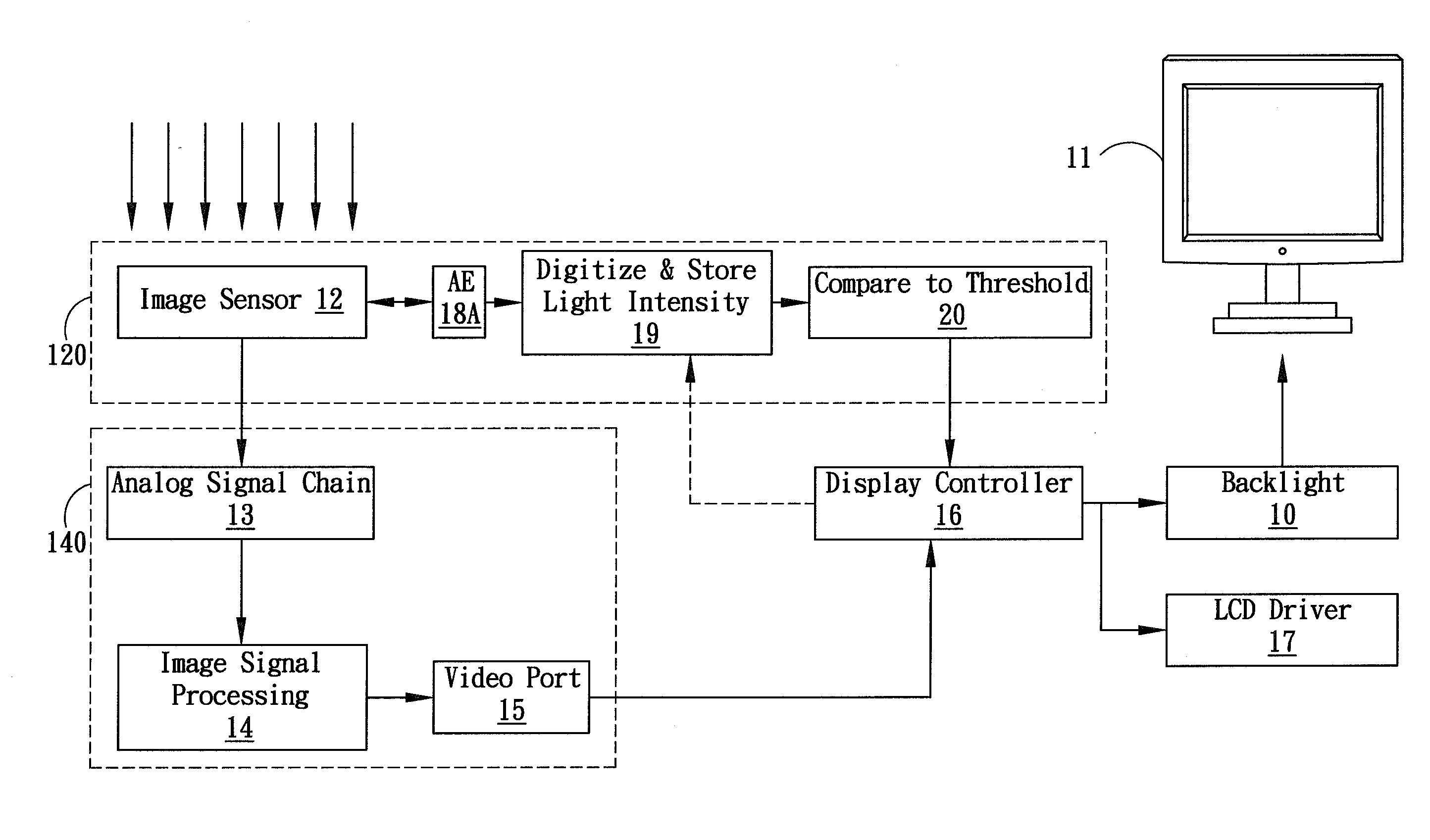
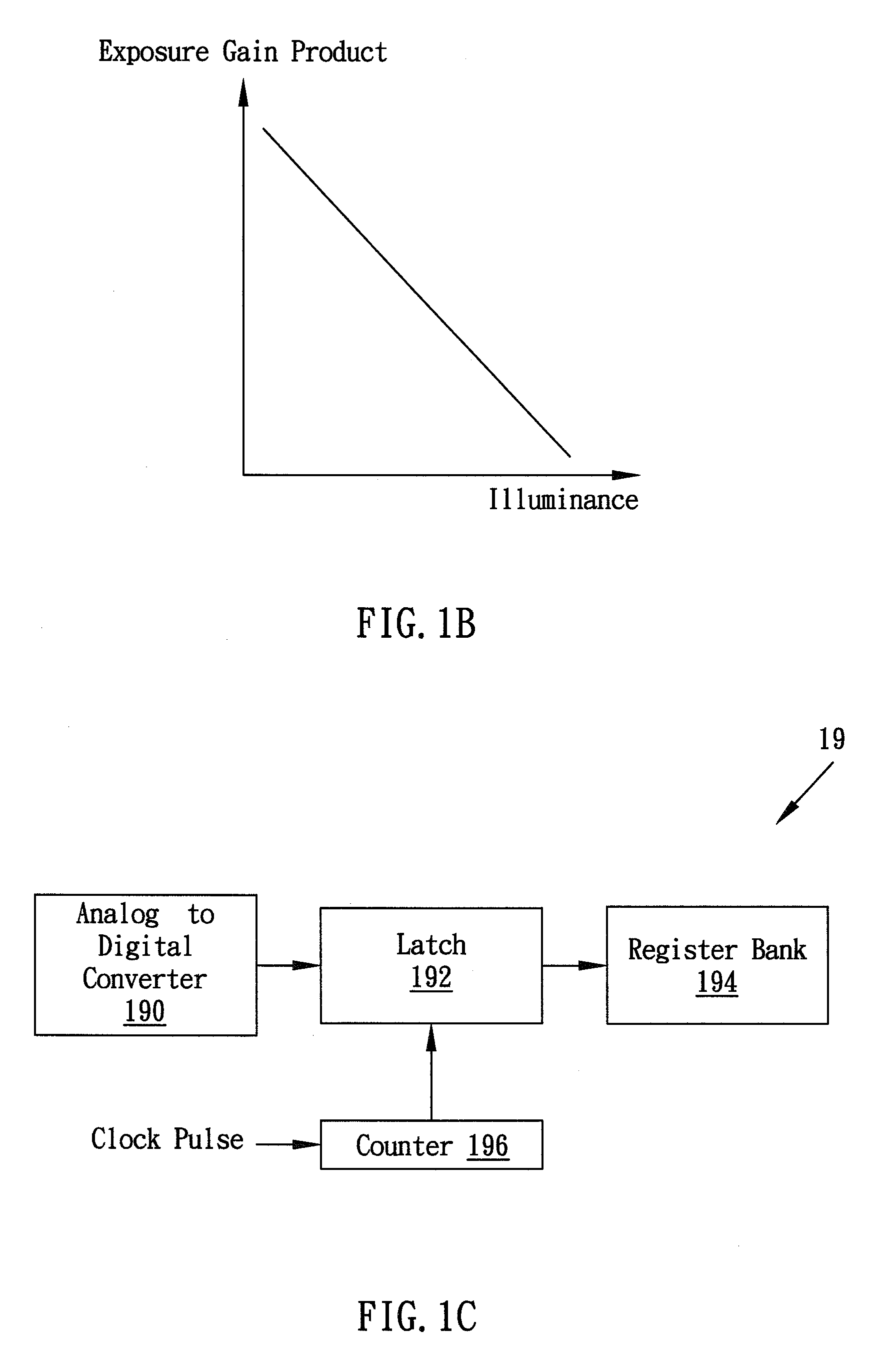
[0023]FIG. 1A illustrates an apparatus for an image sensor 12 with an integrated ambient light meter that can be used to automatically adjust the display brightness of, but is not limited to, a liquid crystal display (LCD) 11 based on ambient light, according to one embodiment of the present invention. In the embodiment, the image sensor 12 is configured, associated with other blocks that will be described later in this specification, to function as a light meter. The image sensor 12 is preferably a complementary metal-oxide-semiconductor (CMOS) image sensor (commonly referred to as CIS) in the present embodiment; however, other image sensors, such as a charge-coupled device (CCD), could be used instead. The integrated light meter operates differently in two modes, which can be referenced as a first mode in which the image sensor 12 is for capturing and outputting image data (or is imaging), and a second mode in which the image sensor 12 is not for capturing and outputting image dat...


PUM


Abstract

The present invention is directed to an image sensor with an integrated light meter that can be used to automatically adjust the display brightness based on ambient light in the environment. According to one embodiment, an automatic exposure (AE) control loop estimates the ambient light when the image sensor is imaging, and the image sensor measures the ambient light when the image sensor is not imaging.

Description

BACKGROUND OF THE INVENTION[0001]1. Field of the Invention[0002]The present invention generally relates to image sensors, and more particularly, to an image sensor with an integrated ambient light meter for controlling electronic display brightness.[0003]2. Description of the Prior Art[0004]Electronic devices utilize display devices to effectively communicate information. Different display technologies, such as Liquid Crystal Displays (LCD), Organic Light Emitting Diodes (OLED), Field Emission Displays, and Plasma Displays, are selected for use depending on the intended application.[0005]The LCD and OLED are flat display devices that have the advantage of being thinner and lighter over conventional displays, such as cathode ray tube displays, and thus receive widespread popularity in a wide range of modern electronic device applications.[0006]The LCD is constructed as transmissive LCD, reflective LCD or transreflective LCD, differing by the relative alignment between light source an...

Claims


Application Information

Patent Timeline
IPC IPC(8): G09G3/36
CPCG09G3/20G09G3/3406G09G2360/144G09G2330/021G09G2320/064H04N25/706
Inventor CHIANG, TONYMITTRA, AMIT
Owner HIMAX IMAGING LIMITED
Learn More