
Coaxial cavity gyrotron with two electron beams

a gyrotron and electron beam technology, applied in the direction of klystrons, electric discharge tubes, magnets, etc., can solve the problem that the gyrotrons cannot provide one exact continuous wave megawatt, and achieve the effect of increasing the output power, increasing efficiency, and greatly increasing the electromagnetic wav

Active Publication Date: 2010-06-10
LIU SHENGGANG +1
View PDF10 Cites 10 Cited by
  • Summary
  • Abstract
  • Description
  • Claims
  • Application Information

AI Technical Summary

Benefits of technology

[0016]In another embodiment the working current is higher than one electron beam gyrotrons therefore the output power is increased.
[0019]In accordance with the present invention a Coaxial Cavity Gyrotron (CCGT) system is composed of a Coaxial Cavity and a plurality of hollow electron beams. The hollow electron beams are produced by an electron gun. The electron beam-wave interaction transfers the kinetic energy of the electrons to the wave, and then the electromagnetic wave is greatly increased. The high power electromagnetic wave is output through an output window. In addition to being used in energy production, the Coaxial Gyrotron system can also be applied in millimeter wave radar systems and other areas in industry. The research of coaxial gyrotrons has attracted great attention in all over the world in order to enhance the output power, increase the efficiency and improve the mode competition.

Problems solved by technology

Assuring the availability of energy sources is a significant issue confronting every country.
However, the current gyrotrons are not able to provide one exact continuous wave megawatt.

Method used


Image

  • Coaxial cavity gyrotron with two electron beams
  • Coaxial cavity gyrotron with two electron beams
  • Coaxial cavity gyrotron with two electron beams

Examples


Embodiment Construction

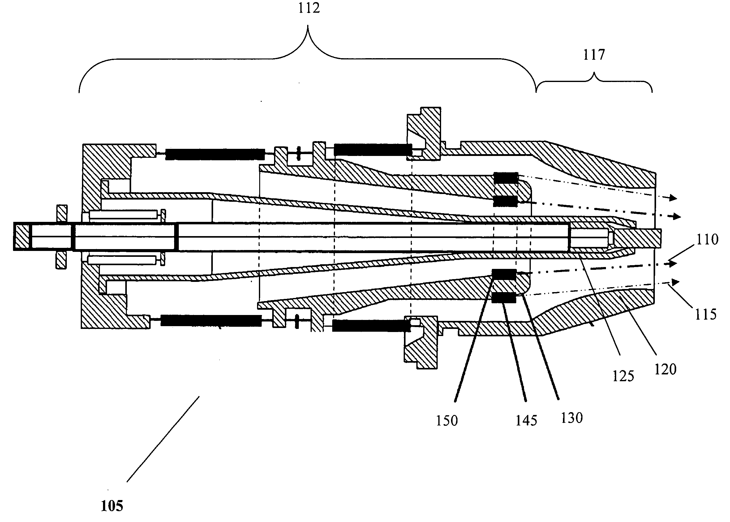
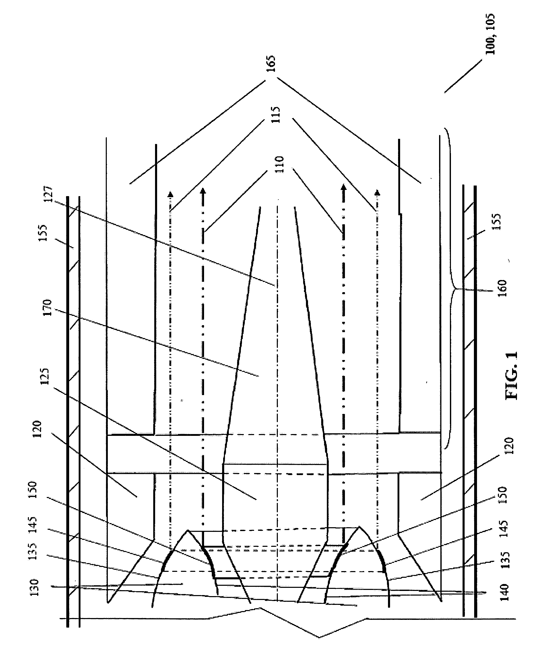
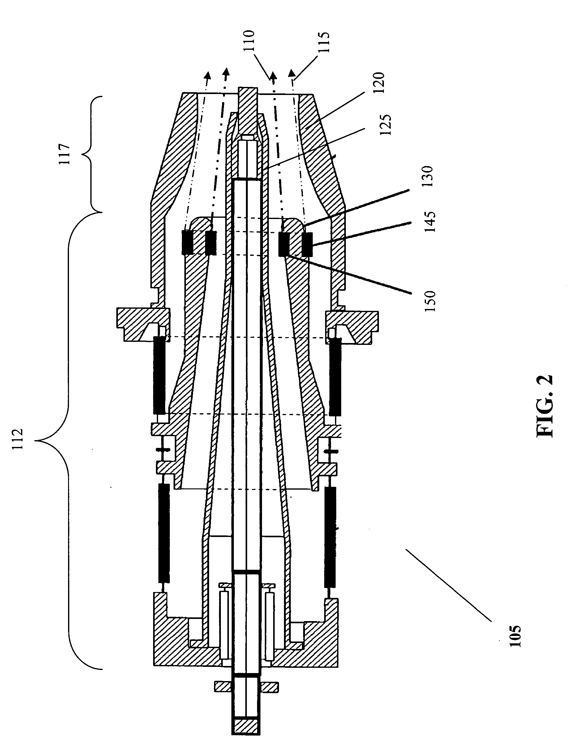
[0026]The aim of this invention is to provide a new gyrotron, a Coaxial Cavity Gyrotron (CCGT) [100] containing a magnetron injection gun (MIG) [105] producing an inner hollow electron beam [110] and an outer hollow electron beam [115]. The MIG [105] has a proximal first zone [112] and a distal second zone [117], a ringed outer anode [120] and a core inner anode [125]. The inner anode [125] resides centrally along a first central axis [127] and centrally within a tubular cathode [130] along a first central axis [127]. The tubular cathode [130] has a cathode outer surface [135] and a cathode inner surface [140].

[0027]The cathode outer surface [135] has an outer ring electron emitter [145]. The cathode inner surface [140] has an inner ring electron emitter [150]. Downstream of the tubular cathode [130] in a second interior zone is a coaxial beam-wave interaction cavity [160] in which the inner hollow electron beam [110] and outer hollow electron beam [115] pass. The CCGT [100] is loca...


PUM


Abstract

A coaxial cavity gyrotron with two electron beams includes an electron gun (magnetron injection gun, “MIG,” with two beams), a coaxial beam-wave interaction cavity and an outer magnetic field tube. The coaxial beam-wave interaction cavity consists of two parts: an outer conductor and an inner conductor. The two hollow electron beams produced by the MIG are located between the outer conductor and the inner conductor. The MIG includes inner and outer anodes, with a single cathode located between the anodes. The cathode further includes two emitter rings which produce the two hollow electron beams. The entire gyrotron is immersed in the magnetic field tube such that the magnetic field profile is the same or similar to that for a coaxial gyrotron with one electron beam.

Description

CROSS REFERENCE TO RELATED APPLICATIONS[0001]The present Continuation-in-Part claims priority from pending U.S. patent application Ser. No. 11 / 639,971, filed Dec. 15, 2006, and Chinese patent application no. 200510022310.4, filed Dec. 16, 2005.BACKGROUND [0002]1. Field of Invention[0003]This invention relates generally to high-power millimeter-wave and terahertz facilities. Particularly, this invention relates to a coaxial cavity gyrotron and an electron gun in the nature of a special magnetic injection gun (MIG) providing two hollow electron beams.[0004]2. Description of Relevant Art[0005]Assuring the availability of energy sources is a significant issue confronting every country. Research and exploration of new energy sources are considered to be of great importance by many countries and scientists. Controlled thermonuclear fusion reaction may provide the most promising solution in the form of a new and clean energy source.[0006]A high power gyrotron is the key device for plasma h...

Claims


Application Information

Patent Timeline
Patent Type & Authority Applications(United States)
IPC IPC(8): H01J25/10
CPCH01J23/075H01J25/025H01J25/02
Inventor LIU, SHENGGANGLIU, CHAOYU
Owner LIU SHENGGANG
Learn More