
Trimmer

Inactive Publication Date: 2010-06-03
ACME UNITED CORPORATION
View PDF95 Cites 7 Cited by
  • Summary
  • Abstract
  • Description
  • Claims
  • Application Information

AI Technical Summary

Benefits of technology

[0011]In an alternate aspect, the present invention relates to a blade guide locking mechanism. The blade guide locking mechanism comprises a rotatable rod having flanges connected at end portions thereof, and an actuator rotatably

Problems solved by technology

Conventional trimmers, and particularly rotary-style trimmers, are often inadequate in at least some aspects.
Specifically, oftentimes the conventional trimmers available and on the market today are generally expensive to own, frequently occupy a large working space (both during storage and operation), and / or are difficult to transport.

Method used


Image

  • Trimmer
  • Trimmer
  • Trimmer

Examples


Embodiment Construction

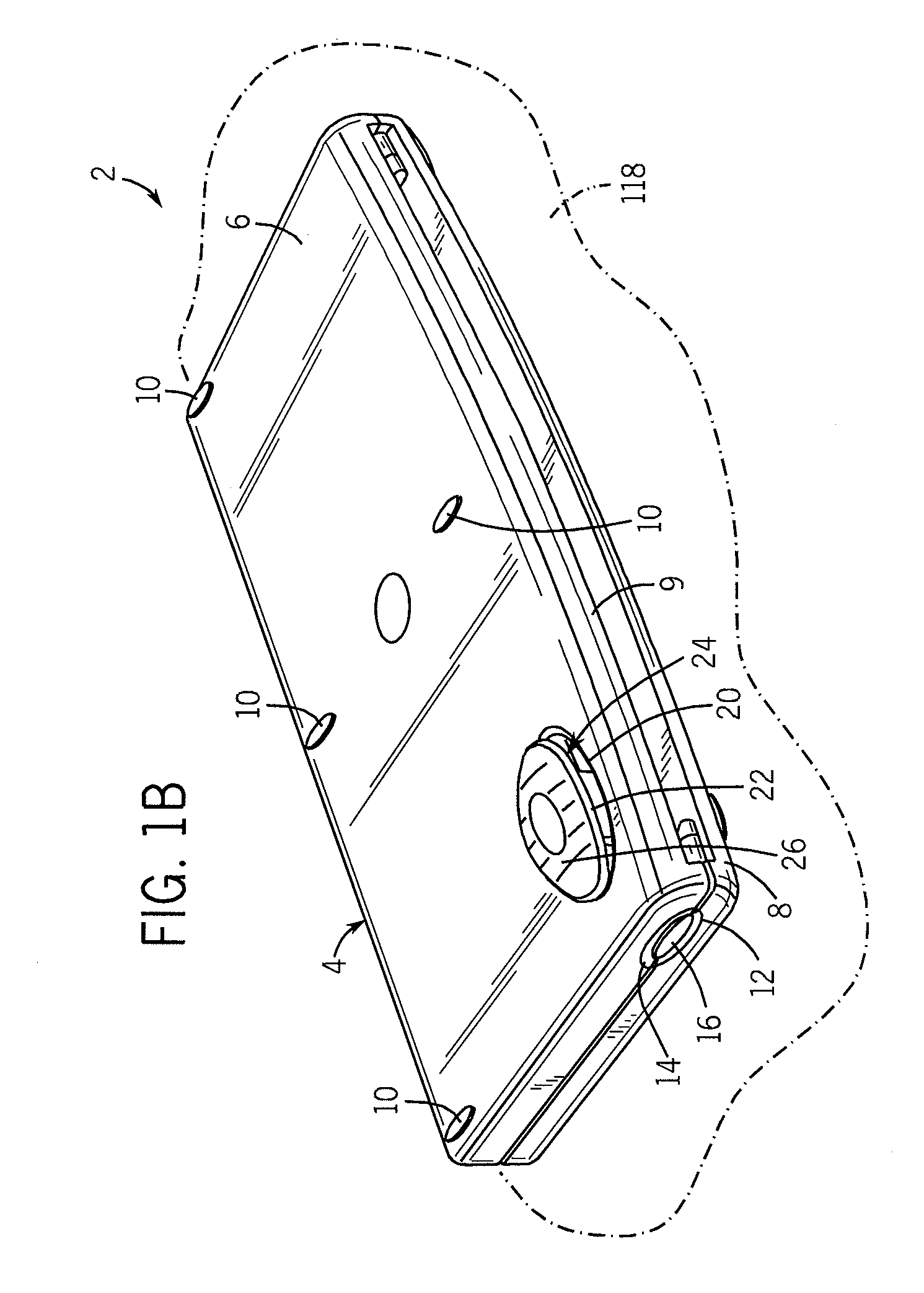
[0027]Referring to FIGS. 1A and 1B, top perspective views of an exemplary trimmer 2 are shown in accordance with at least some embodiments of the present invention. As illustrated, the trimmer 2 includes a trimmer housing 4 having a first housing portion 6 and a second housing portion 8. In at least some embodiments, and as shown, the first housing portion 6 is pivotably connected at least indirectly to the second housing portion 8, in a manner described below. The trimmer housing 4 and particularly the first and the second housing portions 6 and 8, respectively, serve as supports or supporting frames for the trimmer 2, housing various components (again described further below), of the trimmer 2 and also protecting those components during storage and / or transportation of the trimmer.

[0028]As indicated above, FIGS. 1A and 1B show the trimmer 2 in a storage configuration, which as used herein is intended to describe a compact configuration of the trimmer when the trimmer is generally ...


PUM

PropertyMeasurementUnit
Angleaaaaaaaaaa
Stabilityaaaaaaaaaa

Abstract

A trimmer having a trimmer housing is disclosed. In accordance with at least some embodiments, the trimmer housing includes a first housing portion and a second housing portion, the first housing portion being pivotally connected at least indirectly to the second housing portion. The trimmer additionally includes a cutting platform having a first platform connected at least indirectly to the first housing portion and a second platform connected at least indirectly to the second housing portion. The trimmer is configured wherein the second housing portion is substantially stationary and the first housing portion rotates approximately in a 180 degree range of motion from a close position to an open position, such that a flat and continuous cutting surface formed by the first and the second platforms is obtained.

Description

CROSS-REFERENCE TO RELATED APPLICATION[0001]This application claims the benefit of U.S. Provisional Patent Application No. 61 / 098,582, filed Sep. 19, 2008 and U.S. Provisional Patent Application Ser. No. 61 / 192,655 filed Sep. 19, 2008, entitled “Trimmer” each of which is hereby incorporated by reference in its entirety herein.FIELD OF THE INVENTION[0002]The present invention relates to trimmers and, more particularly, to trimmers for cutting paper and related sheet or sheet-like material.BACKGROUND OF THE INVENTION[0003]Devices for cutting and / or trimming sheet or sheet-like material including, for example, paper, cloth, wallpaper and the like are well known in the art. A variety of trimmers, including anvil and rotary type trimmers are commonly available and frequently employed for cutting and / or trimming the aforementioned materials. For example, a trimmer is disclosed in U.S. patent application Ser. No. 10 / 695,429, entitled “Rotary Trimmer” and filed on Oct. 28, 2003, which is in...

Claims


Application Information

Patent Timeline
IPC IPC(8): B26D1/18B26D7/26B26D5/08
CPCB26D1/185B26D7/00B26D2007/0087B26D7/025B26D7/015Y10T83/7747Y10T83/8878Y10T83/95Y10T83/0605Y10T83/7763
Inventor PETERSON, MICHAEL E.CAMPAGNA, AMYMCCAY, JAMES E.CLAY, JOHN K.VERDURA, JAVIER
Owner ACME UNITED CORPORATION
Learn More