
Color electrowetting display (EWD) devices

a display device and electrowetting technology, applied in the field of display devices, can solve the problems of low color efficiency and saturation, alignment between the color filter substrate and the lower substrate, and the increase of the fabrication complexity of the display devi

Inactive Publication Date: 2010-05-27
IND TECH RES INST
View PDF6 Cites 24 Cited by
  • Summary
  • Abstract
  • Description
  • Claims
  • Application Information

AI Technical Summary

Benefits of technology

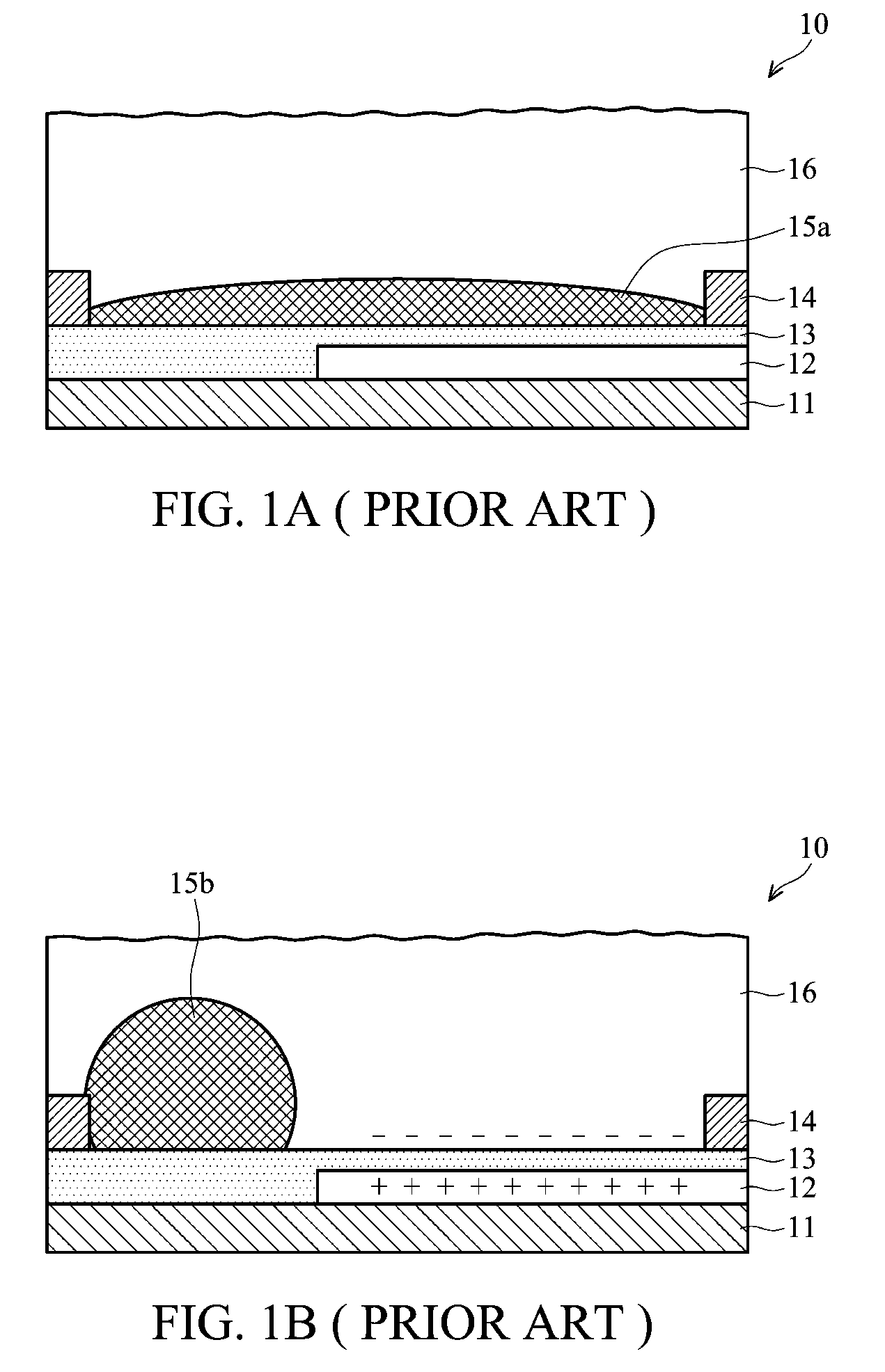
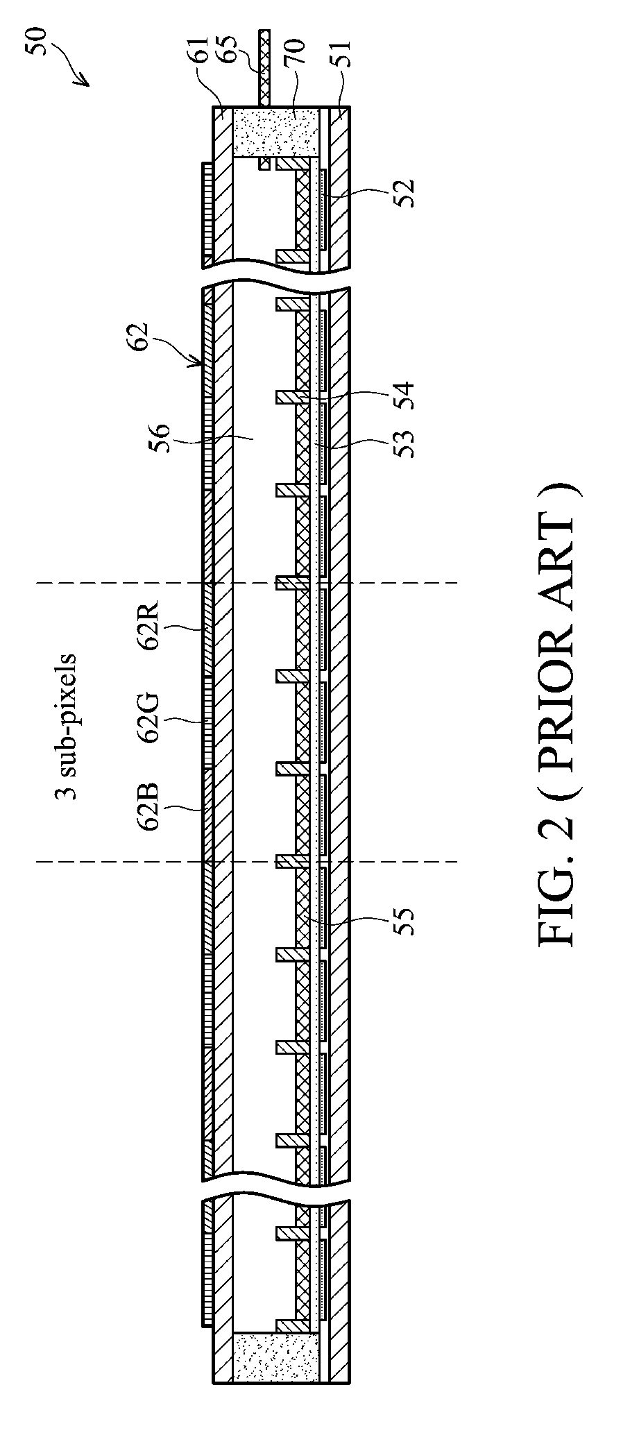
The invention provides a color electrowetting display device with a hydrophilic partition structure that defines a plurality of sub-pixels. The device includes an array of color pixel regions, each consisting of a set of primary color sub-pixels and a black sub-pixel. Each color sub-pixel corresponds to one of different color non-polar fluid layers, which are isolated from each other. The colors of non-polar fluid layer in neighboring sub-pixels are different. This design allows for improved color accuracy and reduced power consumption.

Problems solved by technology

Part of incident light is absorbed by the color filter resulting in lower color efficiency and saturation.
In addition, alignment between the color filter substrate and the lower substrate is so difficult that fabrication complexity of the display device is also increased.
On the other hand, although conventional tri-layered color electrowetting display device can effectively improve color saturation, the display structure is complex, fabrication processes are tedious, and production cost is very high.

Method used


Image

  • Color electrowetting display (EWD) devices
  • Color electrowetting display (EWD) devices
  • Color electrowetting display (EWD) devices

Examples


Embodiment Construction

[0023]It is to be understood that the following disclosure provides many different embodiments, or examples, for implementing different features of various embodiments. Specific examples of components and arrangements are described below to simplify the present disclosure. These are merely examples and are not intended to be limiting. In addition, the present disclosure may repeat reference numerals and / or letters in the various examples. This repetition is for the purpose of simplicity and clarity and does not in itself indicate a relationship between the various embodiments and / or configurations discussed. Moreover, the formation of a first feature over or on a second feature in the description that follows may include embodiments in which the first and second features are formed in direct contact or not in direct contact.

[0024]Embodiments of the invention are directed to electrowetting display devices which display mechanism is achieved by electrically changing surface characteri...


PUM

PropertyMeasurementUnit
thicknessaaaaaaaaaa
thicknessaaaaaaaaaa
thicknessaaaaaaaaaa

Abstract

Electrowetting display devices are presented. The electrowetting display includes a first substrate and an opposing second substrate with a polar fluid layer and a color non-polar fluid layer interposed therebetween. A first transparent electrode is disposed on the first substrate. A second electrode is disposed on the second substrate. A hydrophilic partition structure is disposed on the second substrate, thereby defining a plurality of sub-pixels. The color electrowetting display further includes an array of color pixel regions. Each pixel region consists of a set of primary color sub-pixel. Each color sub-pixel corresponds to one of different color non-polar fluid layers, and each of the different color non-polar fluid layers is isolated from each other. The colors of non-polar fluid layer in the neighboring sub-pixels are different.

Description

CROSS REFERENCE TO RELATED APPLICATIONS[0001]This application is based upon and claims the benefit of priority from a prior Taiwanese Patent Application No. 097145087, filed on Nov. 21, 2008, the entire contents of which are incorporated herein by reference.BACKGROUND OF THE INVENTION[0002]1. Field of the Invention[0003]The invention relates to display devices, and in particular to color electrowetting display devices.[0004]2. Description of the Related Art[0005]Electrowetting display devices are rendered images in accordance with electrowetting or electrocapillary. Briefly, the free surface energy of some fluids is changed due to electric field effects such that distribution area of the fluids can thus change along with the electric field effects.[0006]U.S. Pat. No. 6,967,763, the entirety of which is hereby incorporated by reference, discloses an electrowetting display device. An opaque non-polar fluid in the electrowetting display device converges due to electrowetting effect, th...

Claims


Application Information

Patent Timeline
Patent Type & Authority Applications(United States)
IPC IPC(8): G02F1/167
CPCG02B26/005
Inventor CHENG, WEI-YUANHUANG, CHIEH-YILEE, KUO-CHANGLO, KUO-LUNG
Owner IND TECH RES INST
Learn More